What's new
VORON Design

Register a free account today to become a member! Once signed in, you'll be able to participate on this site by adding your own topics and posts, as well as connect with other members!

Self Sourced Voron Trident 300 Detailed Build Log India Edition

The voron manual/docs mentions the requirements and print settings for 3d printing parts for a voron build.

🟩 Print voron trident build parts myself or PIF ?

Voron India discord has quite a few people who can help you print your voron build parts for you and thats a great option to have as not everyone might have a printer that prints abs or just abs per say.

Printing ABS filament is not like printing PLA which is much easier. What you need is a 3d printer which can
- print at 240 to 260 C nozzle temperature
- bed which can support temperature upto 110 C
- heated chamber which can do at least 40C but some might need ~ 50C
- add to that a good exhast system which can route the fumes it produces outside as it can cause headaches and are not the best to inhale directly thats why many people use some kind of filter before they exhaust out the chamber fumes.

Hence for some PIF or Print It Forward program might be a better choice for some who does not want this hassle in their home.


🟩 Why did I decided to print parts myself and challenges faced ?


why pif is not best approach for me
- do not need all the parts on trident build
- no control to fine tune the print quality for much better quality
- do not get to rapidly prototype new ideas and mods should I need them
- Wait for the shipment to reach you which can be easily two to 4 days just in shipping and the amount of time the person takes to actually print your parts

So I decided to print the parts on my Ender 3 S1 Pro in a make shift cardboard chamber and used Fibreel ABS filament as my first filament of choice. I did not go with esun ABS as I heard mixed opinions on voron discord so decided to skip it.

This is my make shift chamber , I drop a yoga mat in the front as well to seal the front half. Use a camera hooked into octo print to monitor this remotely.
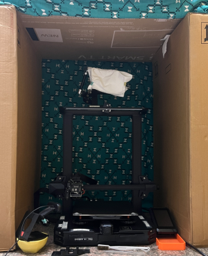
1710321433807.png

I also use a temperature sensor to monitor my chamber temps for ABS printing
picked this from robu https://robu.in/product/lcd-electronic-fish-tank-water-detector-thermometer/
its battery operated and worked really well.
 
@sanketss84 - thanks for writing all this up, particularly your rationales for various choices you made. I’ve recently started a 2.4r2 build, although I’m stopped waiting for printed parts at the moment. Your build log has lots of food for thought, even for a newbie like me.

Really appreciate your efforts here!
Thank you for your kind words. 😃
Best wishes for your V2 build 🥂

I will keep sharing as I continue on my journey of building my first voron.
 
currently part printing is in progress so once i have them ready will resume the build progress log with step by step updates.
 
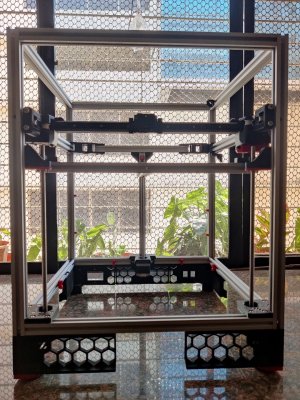
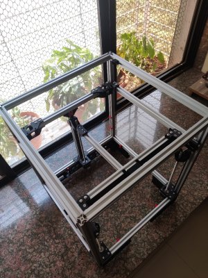
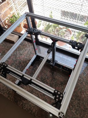
this is where i am right now with my build. will add the various details of each part of the build later as i really have my hands full with other work and also not keeping well.
regarding frame
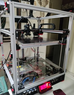
  • frame build and checked if its square and does not tip toe on any of the sides
    • this took the longest of time
    • 🔴 applied loctite blue on screws as I dont want them come out due to vibrations and spoiling the whole build later
    • measure diagonal distance on each side they should be equal or max 1mm off , this is an important check.
    • nero 3d has a video on squaring the frame
  • started with AB mounts and AB idlers
    • originally i was using stock AB idlers but switched to Beefy Idlers
  • then printed the legs and mounted them
  • linear rails cleaned , lubed and checked thoroughly for smooth movement without any binding
    • removed the carriage block from the rails and dipped them in IPA
    • cleaned the rails with IPA using tissues to remove factory oils
    • white lithium grease was used here for lubing the rails
    • this process took a lot of time as well
  • x-axis assembly and gantry movement checks
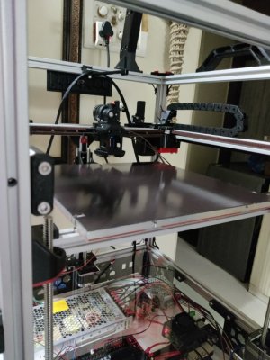
  • installed three z motors , installed bed frame
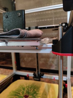
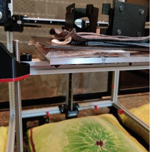
    • i also tested the bed frame for sagging by placing my bed , heater, magnetic sheet , pei print surface and some more weights to check if the lead screw would be able to hold this weight and not come crashing down when the printer is powered off and this test was a success as well.
NOTE:
  • 🔴 take your time with frame being square as this is the base on which your printer will be built.
  • 🔴 ensure your rails are lubed and smooth moving with no binding as this is your motion system


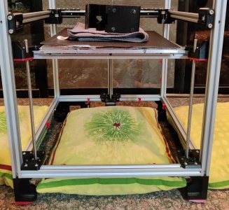
frame_front.jpg


frame_top2.jpg

frame_top1.jpg


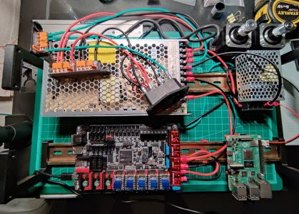
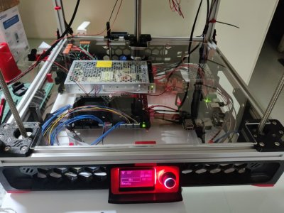
voron_electronics.jpg

regarding electronics chamber
  • choose right wires for mains voltage i used 16awg
    • 20 awg for 5v to pi
    • 16 awg for 24v to octopus , however you can use 20 awg as well for 24v
    • double and triple check all the crimps such that they are held strongly in place and cant come loose 🔴
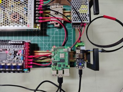
  • mains wiring to both meanwell LRS 200 24 and 25 5 power supply is complete
    • tested 24V and 5V power supplies all rails using multimeter for voltage output
    • turn the small potentiometer on the power supply to tweak voltage level up or down if need be.
    • i got them a little above 24 and 5 V on respective power supplies
    • do this multimeter check atleast for correct voltage output as you dont want to damage your octopus or pi should there be any discrepancy 🔴
  • raspberry pi is flashed with pi os lite and using kiauh flashed klipper , moonraker, mainsailos documented in detail on my blog post
  • flashed klipper to octopus pro using usb-c port documented here
  • tested : powering on octopus pro using 24V using meanwell LRS 200 24 and pi using meanwell 25 5 power supply with shared ground
  • installed TMC2209 stepper drivers and configured printer.cfg just for these stepper drivers and set kinematics to corexy
  • successfully performed stepper buzz on X Y and all three Z stepper motors
    • one thing you need to be careful is check motor data sheet for two motor A and B pairs when wiring.
    • if you get the A and B pairs right you should be good.
    • also check clock wise (CW) and anti clockwise (ACW) direction during motor buzz its 10 movements in total CW and ACW
 
Last edited:
checking if my bed would fall down if printer was powered off.
looks good as its holding everything fine.
the leadscrew is TR8x8

sag test 1 crop.jpg

sag test 2.jpg

sag test 3.jpg
 
not happy with the 3d printed jst connector fan splitter

1711567853603.png

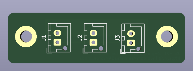
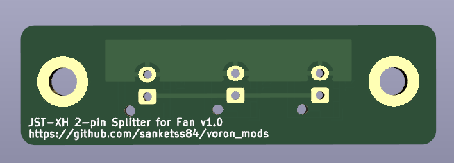
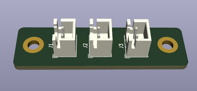
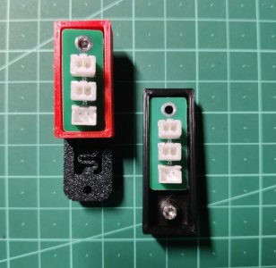
decided to create my own pcb for jst-xh 2 pin connector. It has been a while since I worked with kicad so had to brush up on my skills and spent some time making this pcb today.
I would also like to thank voron community in the electronics channel who actively engaged in providing me with suggestions and feedback on the pcb design.
check the discussion here

this is how the final pcb looks and though it can still use some improvements in design I think for now this will get the job done.

1711568329343.png

1711568338186.png

1711568358424.png


you can pick my open sourced 3 jst-xh 2 pin splitter pcb for fan here should this interest you.

please note there is a xbst repo for random pcbs which does have a pcb for jst xh splitter but that was for 4 connectors and I just need three on my design and I also wanted an opportunity to make my own pcb so I made my own.
 
I got the biggest kick out of you creating your own PCB! I haven’t gotten here yet but will keep this in mind if my own printed part is similar to yours.

The rabbit holes Voron leads us down…
 
I got the biggest kick out of you creating your own PCB! I haven’t gotten here yet but will keep this in mind if my own printed part is similar to yours.

The rabbit holes Voron leads us down…

The whole voron build process is so fascinating that it enables you to learn so many things and helps you meet some really amazing people as well.
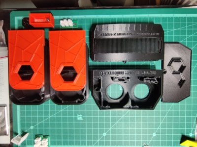
Regarding the pcb this is for the chamber fans where you need to connect two fans to one fan connector on the controller board
 
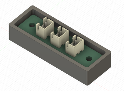
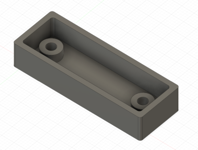
created a housing for the pcb I created and added that as well to the github repo

case with pcb-sm.png

case-sm.png

case top.png

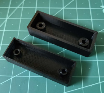
3d printed case to check if its all good.
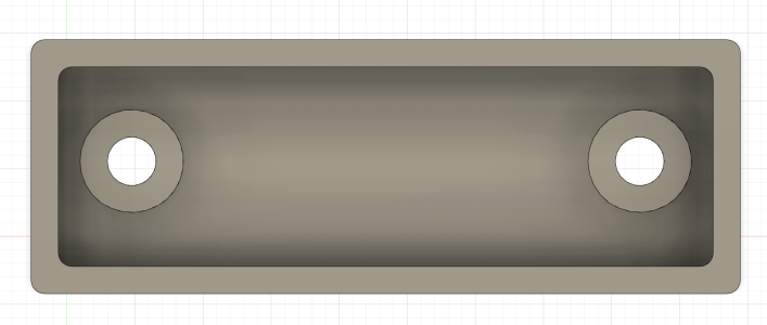
the first case is bottom one which had thinner walls so created a better stronger v2 design, both stls are present in the repo.

3d printed case-sm.png
 
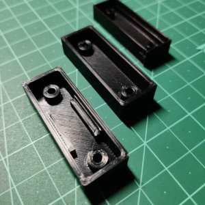
created an updated version of case with some support for pcb in the center area as we insert and remove connectors in the central area of the pcb its better that the case had some support. I have updated the github repo with this updated model.
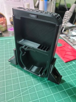
case v3-sm.jpg
 
Thanks to esoterical for his fantastic guide on setting CAN this step went smooth and also for helping me on voron discord with few of my queries.
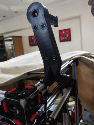
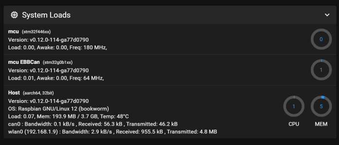
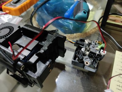
Finished setting and testing CAN using BTT EBB36 + BTT U2C Can Adapter and Pi.
Tested fan and thermistor on the EBB36 and they seemed to connect and work as intended.

NOTES
  • 🔴 when you are doing the molex microfit can wire from ebb36 to u2c check which wire goes where and double and triple check everything as the wire orientations are not same on both boards.
  • ensure that 120R jumpers are plugged in on both u2c and ebb36 (for me I only have one can toolhead board so those are my can start and end nodes)
  • it is not necessary to flash katapult to ebb36 but what it allows is for you to flash klipper to ebb36 using CAN network and if in the future should you need to reflash updated klipper firmware you can easily do it again over can instead of flashing klipper via usb.
ebb36-klipper-katapult-flash-5.png

ebb36-klipper-katapult-flash-7.png

ebb36-u2c-pi-can-2-sm.jpg

quick testing of 4010 blower fan interfaced on EBB36 was a success.
ebb36-u2c-pi-can-1-sm.jpg
 
Last edited:
today was all about fixing mistakes in the build. a lot of rework but its ok its also part of the build process. its important to get things right else they can cause unnecessary headaches ahead.

  • brought drag chains 10x10mm and 10x15mm instead of 3d printing the panzer drag chains from voron mods as the prints were just not latching properly and had very little flex.
    • so purchased non openable drag chains as its quick and fast to unscrew both ends and pass wire through them rather than opening each hook for each chain.
  • dragon burner
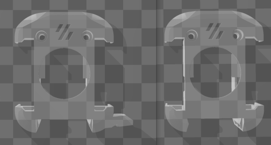
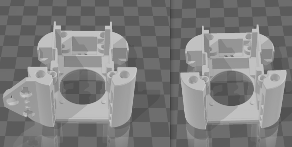
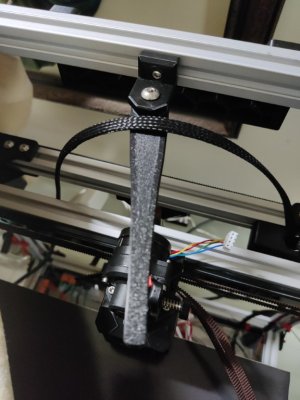
    • the cowl I had printed with was the one with klicky probe fixed on side , need to print fresh no probe cowl
    • even the carriage base section was not hitting my x-endstop switch so needed to print and test carriage base part with end stop
    • redo the x-gantry as carriage was getting blocked at the end on right so I had to undo the x-gantry screws and that needed to remove the belts to recheck smooth rails movement from front to back.
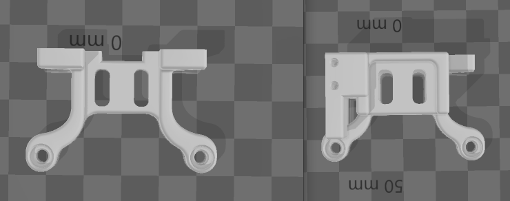
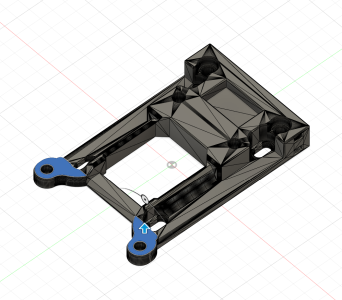
  • testing cartographer cnc metal bracket for steapth burner to dragon burner 3d printed adapter which was also not mounting correctly so I had to make some edits to this model in fusion to fix the mount, this is a work in progress.

Dragon Burner corrections

1712354691255.png

1712354766172.png


so this klicky probe cowl on left was hitting the front right lead screw.

1712354519500.png

this bottom carriage mount on left replaced with on on right so that my x end stop can be hit.

cartographer fusion fix.png

cartographer adapter fix and test with varying heights. will share more details on this as I get it sorted.


will add more images tomorrow as its been a long and tiring day for sorting things out
 
Last edited:
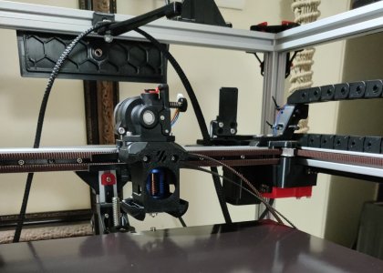
updating progress after a while.

printing parts , testing various mods and idea, re-ordering finished spares is what I was doing for past few days. add to that super hot weather around 36 to 38 C slowed things a bit..

progress
  • set belts
    • this took a lot of time to get right , I had remove and redo the belt several times to ensure each and every pulley was aligning properly also match the number of teeth on top and bottom to be same.
  • setup electronics chamber
  • test stepper buzz on X Y Z
  • test homing on X Y Z
    • getting the z end stop pin right was the trick with z endstop
  • check the toolhead spans the entire X Y axis all corners without obstruction.
  • check the bed is able to stay put when powered off
  • check the bed moves up and down without any obstruction while moving on z axis
current state
  • X Y Z are homing successfully.
  • extruder is extruding and retracting successfully via EBB36 CAN (tested without hotend).


IMG_20240428_220842_1-med.jpg

IMG_20240428_220858-med.jpg

IMG_20240428_220907_1-med.jpg

IMG_20240428_220918-med.jpg
 
Last edited:
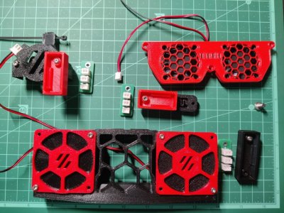
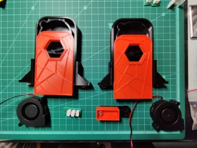
custom jst xh pcb for use with dragon burner dual 4010 blower , dual chamber fans, dual octopus pro stepper driver cooling.

pcb gerbers can be found here.

IMG_20240428_230803-med.jpg

IMG_20240428_230819-med.jpg
 
mods
  • annex engg panel clips , because of screw less design (github link)
  • ramalama2 octopus pro fan duct , 2 x 4010 fans (github link)
  • 4010 fan clip on holder for pi (printables link)
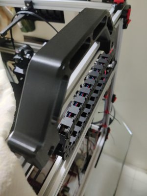
  • trident sturdy handles which uses m3 screws instead of m5 (printables link)
  • spool holder, its sturdy and sits on top in center (voron mods link)
  • the filter (printables link)
    • using two singles on left and right
    • printed the nevermore v6 earlier and did not like the mounting clip and the lid was a bit too tight so discarded it entirely.
    • the filter also has some variations

sturdy voron handle is super helpful once you start assembling the electronics chamber as there is not much area to hold and life the printer

sturdy handle with m3 screw holes-med.jpg

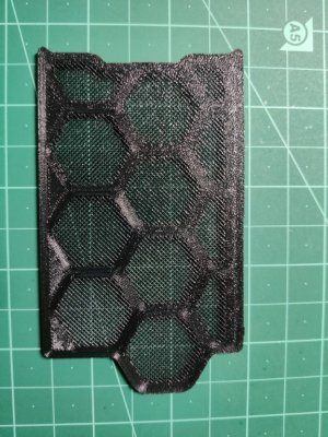
figured out how to add grills to skirts and printed skirts with this grill to avoid dust from flowing inside freely.

skirts with grill-med.jpg

this nifty print helps direct the ptfe tube as well as support the can bus wire from moving in random places when we enclose the top panel and there is not much room for the ptfe tube to move properly. this print should help directing it.

ptfe tube guide-med.jpg

nevermore v6 Vs the filter singles to be placed in left and right bottom.

nevermore vs the filter-med.jpg

the filter and two generic 5010 blowers

the filter-med.jpg

will be mounting this on 2020 extrusion with the help of these support clips

the filter with support stands-med.jpg

spool holder , nice and sturdy and shall help the spool sit on top vs on the side.

spool holder-med.jpg
 
Alright guys finally got Klicky working and performed my first z-tilt or three point bed leveling (the most satisfying thing I was looking forward to check on my Trident build the moment I decided to build it as my first Voron, watching this come to life was sheer joy).

I printed both Klicky and Klicky NG and assembled both versions. Klicky NG was a bit of a pain to assemble however I have not found a satisfactory way to mount it alongside dragon burner so for now I am going with original Klicky.

Voron Trident Build - XYZ Homing Klicky Dock Undock

Voron Trident Build - z-tilt or three point bed leveling using Klicky Probe

This can only look best on video. :) Here goes my first video post.
 
Top