VORON Design

You are using an out of date browser. It may not display this or other websites correctly.
You should upgrade or use an alternative browser.
You should upgrade or use an alternative browser.
Formbot V0.2 Kit Build - Darth Voron (S/N V0.2633)
- Thread starter Mxbrnr
- Start date

robrob
Active member
BT- you can check my full configs on GitHub! (there is a link to the instructions on how to sync them to git in the readme; it's awesome- just be sure to add your octoeverywhere settings to the gitignore so your API key isn't publicly exposed, lol ask me how I know)

 github.com
warning: I haven't fully setup any of the macros other than the "backup config" one, so don't trust /use them!
GitHub - rangersnuggles/Voron02configs
Contribute to rangersnuggles/Voron02configs development by creating an account on GitHub.
github.com
warning: I haven't fully setup any of the macros other than the "backup config" one, so don't trust /use them!
BallisticTech
Active member
Thanks @robrob and @Mxbrnr .
I see my currents and Sensorless sensitivity is pretty close to Rob's.
There's a little blurb in the _HOME_X and _HOME_Y macros about setting the homing current to
I read 70% less as meaning 30% of run_current which would be like .21
But with a homing current that low I got really bad/inconsistent results when setting the sensitivity.
I think they actually want a Percentage as a decimal here?
If you look at the macro they then set the current for homing to be Home_Current * Run_Current...???
Then at the end of the Macro set the current back to the original Run_Current.
I just don't think the instructions match what's actually happening in the macro... Or am I just super confused here?

In the TMC Sensorless guide on Klipper docs they directly set the current to the set HOME_CUR variable then set it back.

I see my currents and Sensorless sensitivity is pretty close to Rob's.
There's a little blurb in the _HOME_X and _HOME_Y macros about setting the homing current to
Code:
{% set HOME_CURRENT = XX %} # replace the XX with a current value that is about 70% less than your run_current value for X and YI read 70% less as meaning 30% of run_current which would be like .21
But with a homing current that low I got really bad/inconsistent results when setting the sensitivity.
I think they actually want a Percentage as a decimal here?
If you look at the macro they then set the current for homing to be Home_Current * Run_Current...???
Then at the end of the Macro set the current back to the original Run_Current.
I just don't think the instructions match what's actually happening in the macro... Or am I just super confused here?
In the TMC Sensorless guide on Klipper docs they directly set the current to the set HOME_CUR variable then set it back.
StackingDeezLayers
New member
What mount did you use for the Manta E3 EZ? I plan on using this motherboard along with a Formbot kit too. Along with that question, does the screen just plug in to? Just a USB C plug?
Mxbrnr
Active member
This is the one I used. I'm not a big fan of attaching things with VHB tape, but this seems the best solution I could find for my desires.
As for the screen, I actually don't know because I don't use mine; never had any intention of using it, so never hooked it up or programmed it.
As for the screen, I actually don't know because I don't use mine; never had any intention of using it, so never hooked it up or programmed it.
Attachments
robrob
Active member
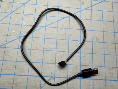
....with a Formbot kit too. Along with that question, does the screen just plug in to? Just a USB C plug?
The screen plugs in via USB, but the included USB-C cable is monstrous looking when it pokes out the side on the front of your skirts; I hacked up an old USB cable and connected it to the backside of the screen with Dupont connectors. after you flash the firmware it shows up alongside your MCU in Klipper.
Attachments
Mxbrnr
Active member
Build Update:
Here are the mods I have so far made to my Formbot V0.2 kit...
1) Swapped out the stock build BTT SKR Pico and BTT Pi for a BTT Manta E3EZ & BTT CB1 combo. I found this change was needed to make use of the built-in chamber thermistor in the V0 Umbilical mod that comes with the kit, and to add the extra fans listed below.
2) Added a CPU fan to the BTT CB1. I found that while printing the CPU temp would regularly approach or exceed 50*C. This fan has thus far kept the temp to around 40*C.
3) Added a fan underneath the Kirigami bed to circulate the bed heat for better chamber temp stabilization. My testing has shown that with this the chamber can reach upwards of 45*C in about half the amount of time. However, I also found that a fan speed in excess of 35% pulls too much heat away from the bed for the stock heater to keep up until temps have stabilized, then it can go up to 50%, but no more.
4) Added a cover plate for the z-axis lead screw floor gap.
5) Added carrying handles to the tophat.
Future Mods Planned:
1) Chamber LEDs
2) Dragon Burner toolhead with Rapido HF hotend
4) Nozzle LEDs
5) Replace & relocate chamber thermistor (the V0-Umbilical built-in one is surprisingly inaccurate)
6) Upgrade bed heater to 100W AC (will additionally require an upgraded 200W PSU to handle the increased power consumption)
Mxbrnr
Active member
My home values were a bit lower (49 and 53), but those are easily affected by belt tension and motor current, so that can explain that. The run currents do look about right; mine are set at 0.8.@Mxbrnr @robrob
Does this look close to what you have for starting run currents, and sensorless homing values?
View attachment 2699
Last edited:
Mxbrnr
Active member
Build update, Sept 30:
Well, what was originally planned as a simple refresh to the V0.2r1 update and a couple of upgrades turned into a nearly complete rebuild, but Darth Voron is ready to resume his reign of terror.


Well, what was originally planned as a simple refresh to the V0.2r1 update and a couple of upgrades turned into a nearly complete rebuild, but Darth Voron is ready to resume his reign of terror.
- Replaced ALL the 3D printed parts on the machine. The parts that I got from the PIF program fell petty short of my quality standards, and as I found out, short of the PIF Program standards as well. Many of the parts had various failures to include layer adhesion, wall/surface gaps, dimensional accuracy, and even blobs. I was able to use the machine to print its own replacement parts before disassembling it for the rebuild, and I am much more pleased with the outcome and much more confident in them. Filaments used were Overture ABS in Black, and Flashforge ASA in Iron Gray. Here is a sampling of the issues seen on nearly every part that came in my kit from the PIF program; no fault to the PIF program, as it may be just an individual supplier problem, but like with anything else, always inspect the work to make sure it is to standards...
- Changed the kit 60W build plate/heated bed and power supply with the LDO polyimide 100W bed heater kit (including 200W power supply required for the higher power bed). Bed temps are attained much faster, are much more accurate, and heat the chamber much faster and to higher temps now along with the use of the bed heat circulation fan I installed previously. All bed and bed fan wiring is now run via Wago connectors mounted to the inside of the Kirigami bed frame, rather than being directly wired all the way to the controller board, making removal of the bed from the machine much easier if ever needed.
- Installed a different floor/z-drive 3D printed cover plate.
- Updated all Kirigami bed 3D printed parts with latest revision.
- Installed Kirigami bed "V0 Stealth Bumper" face plate
- Installed "arrow" front idler tophat cam locks
- Installed larger bed screw thumb nuts
- Changed the stock Mini-Stealthburner toolhead to the Dragonburner toolhead combined with the Sherpa Mini extruder and BMG RIDGA extruder gears. Unfortunately, the Sherpa-Mini's ability to retain the end of a Bowden tube in its housing is pretty atrocious, it really needs to accept a coupler for better retention. Apparently a user requested this mod a couple years ago even and made it themselves, but Annex Engineering has still not implemented it as an official option, so it only remains as a user-mod for an older version of the housing which is not compatible with the BMG RIDGA. Seems I will need to modify it myself to make that a reality.
- Disconnected the V0 Umbilical PCB thermistor and installed a generic hotend thermistor mounted to the top of a z-axis extrusion for use as the chamber temp probe. The PCB thermistor was rather unreliable due to its mounting on the PCB directly above the electronics compartment, which allowed its temp reading to be significantly affected by the ambient air in the electronics bay. Note that the new probe needed to be mounted to the outboard side of the extrusion to keep it out of the airflow coming off the hotend in order for it to get the most accurate reading for the actual ambient air temp inside the chamber.
- Installed foam tape to clear acrylic panels (excluding door) where they seal against extrusions.
- Changed stock tophat hinges to "lift-off" hinges.
- Removed stock front skirt display and changed to "blank" skirt.
- Installed chamber LED strips


Last edited:
I just noted the less than optimal setup for the Picobilical "chamber" thermistor myself. With the printer sitting idle, open (no door or tophat yet) I saw the thing reading 30.5C. Yeah, it wasn't that hot in the room. I dug around and found that the thermistor is on the frame PCB, which really makes it an electronics enclosure thermistor, not a print chamber thermistor. Makes me wonder why it wasn't either omitted or put on the tool head PCB. In any case, I've already planned for the same mod as you are. I believe I can use the gpio17 port on the SKR Pico for it--it appears Picobilical frees that one up.
Mxbrnr
Active member
Build update, Oct 5th:
As one of the first calibrations on the rebuilt machine, I purchased the Provok3D nozzle-mount ADXL345 for running input shaper, and after doing so, it's hitting 22k acceleration! The default setting is 2k, and previously I had done input shaping the old fashioned way with a test print and dial calipers, which got me up to 4k on the stock machine. Now we are more than 5 times that quick! The hotend is still limiting it to around 200mm/s print speed (12-15mm^3 volumetric flow) , but a simple upgrade to a CHT nozzle should get to near double that, which will probably be more than enough for my uses. Surprisingly, changing the tool head from the Mini-Stealthburner to the Dragonburner showed that their weights between the two are as near as makes no difference, though for its weight the DB has bigger cooling fans and is mounted more rigidly. Modifying the Sherpa Mini housing to accept a coupler for a reverse-Bowden tube will probably eliminate the remaining weight difference. I will admit that I like the look of the Mini-SB much more (especially in its multi-color variants) and it has better wire routing, but the part cooling on the DB is SIGNIFICANTLY better.


As one of the first calibrations on the rebuilt machine, I purchased the Provok3D nozzle-mount ADXL345 for running input shaper, and after doing so, it's hitting 22k acceleration! The default setting is 2k, and previously I had done input shaping the old fashioned way with a test print and dial calipers, which got me up to 4k on the stock machine. Now we are more than 5 times that quick! The hotend is still limiting it to around 200mm/s print speed (12-15mm^3 volumetric flow) , but a simple upgrade to a CHT nozzle should get to near double that, which will probably be more than enough for my uses. Surprisingly, changing the tool head from the Mini-Stealthburner to the Dragonburner showed that their weights between the two are as near as makes no difference, though for its weight the DB has bigger cooling fans and is mounted more rigidly. Modifying the Sherpa Mini housing to accept a coupler for a reverse-Bowden tube will probably eliminate the remaining weight difference. I will admit that I like the look of the Mini-SB much more (especially in its multi-color variants) and it has better wire routing, but the part cooling on the DB is SIGNIFICANTLY better.
Last edited:
FYI, I looked at the pinouts on the SKR Pico more and thought about it more. gpio17 probably won't work--that's just a fan on/off. It looks more like gpio 26 or 27 (THB, TH0) might work since Picobilical freed those up. Just semi-educated guesses for now.
Thanks for that comparison on the tool heads. I doubt I'll bother looking much at Dragonburner then--I'm not chasing grams. As it is, I'll have to tear my MiniSB down as the right side part cooling fan seems to be binding up.
Thanks for that comparison on the tool heads. I doubt I'll bother looking much at Dragonburner then--I'm not chasing grams. As it is, I'll have to tear my MiniSB down as the right side part cooling fan seems to be binding up.
BallisticTech
Active member
I believe the thermistor on the VO frame board is on the top of the PCB when it's mounted. Meaning it is somewhat indicative of the chamber temperature.FYI, I looked at the pinouts on the SKR Pico more and thought about it more. gpio17 probably won't work--that's just a fan on/off. It looks more like gpio 26 or 27 (THB, TH0) might work since Picobilical freed those up. Just semi-educated guesses for now.
Thanks for that comparison on the tool heads. I doubt I'll bother looking much at Dragonburner then--I'm not chasing grams. As it is, I'll have to tear my MiniSB down as the right side part cooling fan seems to be binding up.

I've heard people mentioning using a non-thermistor pin on an SKR Pico to read the chamber thermistor but I still haven't seen any posts noting how to get it to work. I think thermistor pins generally have some extra circuitry necessary to read the thermistors correctly.
I added a Klipper Expander board to my build to read the thermistor chamber, drive fans for the Nevermore, and drive extra neopixels.
Mxbrnr
Active member
Build update, Dec 12:
Hit right around 100hrs of print time and started running into issues with the V0-Umbilical mod included in the Formbot V0.2 kit. I know it is either a wiring or connector issue causing my hotend heater to lose power. The umbilical cable is much to stiff, and that combined with it's length causes it to push against the tophat almost constantly, all together putting quite a bit of stress on the wire ends and the PCB receptacles. Sadly, this is just one more thing I have recently discovered that I find less than impressive about the Formbot kit, though I would say that it is still very much worth the price and I still love this thing; wouldn't trade it for anything else (except a V2.4 or Trident? haha).
I removed the heat shrink and sheathing from the harness which has already made the bundle much more flexible, and have found some strain relief mount mods to try. If that doesn't work then I will likely end up changing the wiring out with something even more flexible.
Frame-side strain relief and connector support... https://www.printables.com/model/661256-voron-v02-umbilical-pcb-strain-relief-and-molex-su
Toolhead-side PCB mount with strain relief (for Dragon Burner and Sherpa-Mini)... https://www.printables.com/model/470918-v02-umbilical-pcb-mount-for-dragonburner-and-sherp
Last edited:
Mxbrnr
Active member
Update, Dec 04, 2024:
After several months of downtime while I focused on other life priorities, I finally got around to what will in all likelihood be the last modifications to my V0.2. I now have over 500hrs of use on the machine since I first built it, and it has been a pleasure, even when also a bit of a pain, haha. Here is the list of latest mods with photos and links where possible.
After several months of downtime while I focused on other life priorities, I finally got around to what will in all likelihood be the last modifications to my V0.2. I now have over 500hrs of use on the machine since I first built it, and it has been a pleasure, even when also a bit of a pain, haha. Here is the list of latest mods with photos and links where possible.
- ALL parts printed/reprinted in Polymaker PolyLite ASA Black and Flashforge ASA Iron Gray
- Edited the V0 display config to change the "Feed Rate" into chamber temp, and changed the glyph for the nozzle temp to match the one in Mainsail.
- Re-printed display faceplate in dual-color using a pause and manual filament swap

- Upgraded the Dragon Burner toolhead to the latest version (v8)
- Installed modified Sherpa-Mini front plate with provisions for ECAS collet and filament runout micro-switch (switch not yet installed, may end up not doing it since it's not really needed and adds complexity)
- Installed Adafruit neopixel nozzle LEDs
- It would seem these don't like running in a 70C chamber while also being so close to the hotend. They have developed flickering issues that are only present after about 1hr during printing. I will most likely end up removing these. While they are a nice feature, I am not accepting of their lack of reliability, especially for the added complexity.

- Upgraded hotend to a Haldis Red Lizard K1 Pro HF
- This hotend comes with a a CHT-style hardened steel nozzle, and claims to have a max flow rate of around 44. In testing the way CNC Kitchen does using a milligram scale, I found that ASA pushed through at 270C temp barely made it to a flow rate of 24 before experiencing extrusion drop-off. At 260C it wouldn't even get to 20. Disappointing, but still much better than the 10-12 I was getting on the SF hotend. I also discovered after the fact that this hotend comes with a 60W heater, which is low enough that it fails to maintain 250C when I have the part cooling fans (GDSTime 4010 blowers) cranked up to 100%. That was very shocking, but livable since it is rare the fans are ever on that high, and only in short bursts (overhangs and bridges). Haven't tested it to see if it will maintain PLA print temps with the fans, so might end up having to change it out for something with an 80W or better heater. Works good for now though.

- Swapped the V0-Umbilical system for a BTT EBB36 toolhead board after dealing with multiple wire and connector failures on the V0-Umbilical. Built and crimped the wiring harness myself with 20 and 22 AWG silicone wiring. Swapped out the frame-side PCB motor plate panel for one with a PG7 connector. Modified the original plate design to remove the PTFE tube hole since it was able to fit down the PG7 connector alongside the wire bundle. Makes for a much cleaner look
- Installation was straight forward using the Esoterical guide, which I am supremely thankful for. Never would have been able to do it on my own without that...
- This had the added benefit of freeing up several ports on the control board, which made room for a Nevermore filter and skirt fans. Only 1 part cooling fan port exists on the toolhead PCB, so had to create a custom connection splitter to wire the 2 part cooling fans in parallel to that port.
- With the V0-Umbilical frame PCB now gone, I had to rewire my chamber lights via Wago connectors so they could be run in parallel to the single RGB port on the MCU


- Installed Nevermore Micro v6
- I incorporated this into my print start macro to help with chamber heat circulation. It did not INCREASE the speed at which the chamber heats, but it does make it so that I can reach around 57C on my chamber temp during my heat soak, as opposed to the 52C I was getting without it. Not a huge difference, but I think it helps with the consistency of the temp throughout the chamber.

- Swapped out the stock front door for the Mini-Fridge (Clicky-Clack) door
- Had to custom modify the inner door latch for fitment since the LDO door kit came with horizontal extrusions cut 1mm longer than the printer frame extrusions supplied in the Formbot kit that the printer started out as.


Last edited:
Mxbrnr
Active member
- Installed extended front feet, and skirts/display mount to match the Mini-Fridge door
- Had to modify them with an extra 2mm of height to clear the door (another dimension issue with the LDO door kit compared to Formbot printer frame). Added 1.8mm accent mesh backing to skirts as well. Thanks to "Driftrotor" for the original mod design that I built off of, and the instruction video about how t add the mesh backing.


- Installed fan side skirts (with accent mesh)
- Had an issue with seemingly random printer power-offs with no warnings or errors. Turned out to be the 200W Mornsun PSU overheating. I believe this to be caused by a combination of the PSU's internal heat production, conductive heat from the 70C chamber transferring to the PSU (since it is mounted to the underside of the bottom chamber panel, and a lack of thermal mass around the PSU in the bottom electronics bay from both a small volume space and high altitude (I live at 6000ft MSL). The PSU was getting hotter than the heated bed at times, so I can definitely see 80-100C being the case. Adding skirts with a couple of 3010 axial fans (one blowing directly into the PSU, and the other blowing around its side across the vents, creating a mild venturi effect) seems to have entirely solved that issue. The fans are set up in my config so that they only turn on when the bed or hotend heaters are active, or when the associated thermistors register temps over 45C. Only two fans are installed on the left side, but for symmetry the same skirts are installed on the right, and I created some cover plate blanks for the empty fan ports. Custom built a connection splitter to wire the fans in parallel to the same MCU port.
- The side skirts, back skirt, and both rear feet were modified to add 2mm of height to match the front skirts/feet. I think that has also helped with the PSU by allowing more space for airflow.
- The accent mesh on all the skirts was done using hexagon infill at 30%. Thanks again to "Driftrotor" for the original mod design.


- Installed hinged mesh panel for back electronics
- With new panel, saw an instant temp drop on both my CPU and MCU, from around 60C to now not more than 50C

- Added "modesty" panels to the sides of the back electronics bay to improve visual aesthetics
- Swapped out all linear rails and nut rails from the kit-supplied stock Vivedinos and BOM prints to West3D Class-H rails with stainless steel T-nut bars.
- These new rails have carriages with grease ports, allowing them to be re-greased without removing from the rail. As a side note, the Formbot kit comes with 1 rail that has a higher bearing preload and is meant for use in the X-axis, but as it turns out was mislabeled, and had been installed as one of the Y-axis rails. Oh well, not a problem anymore.
- I also ran into an issue where the printed nut rails had suffered from heat creep to the point that I was having to re-tighten the linear rail screws fairly often. With the new stainless steel bars not only is the screw down force more spread out within the extrusion, but I was also able to use Loctite to make sure they stayed tight.


- Installed double-shear A/B motor mounts (thanks yet again to "Driftrotor"). These alone provided bump of 7.5% and 12.5% to my top end speed and accelerations respectively. While the input shaper results remain virtually unchanged, the now increased margin between actual printing speed/accel and top speed/accel is a good indicator that the motors are not working as hard, which lends to reliability and longevity. The motors are still only running at 24V/0.8A of power, and I am getting a speed of 700 at 45k accel before skipping occurs (up from 650/40k). The hotend and input shaper are of course the big limiting factors in the printer's capabilities, since they have me throttled down to around 225 and 14k, but at least I can travel fast. I am mostly interested in the reliability and longevity part anyway.
- Fun fact: it's hard to imagine what these speed/accel numbers mean. 700@45k is the toolhead being flung around with 4.5Gs of force. For comparison, the Top Fuel dragster car 1000ft record is 0-338mph in 2.8sec; that's an average of about 4.2Gs. An F-18 fighter jet that is catapult launched off an aircraft carrier from 0-160mph in under 2sec is about 3-4Gs. Pretty wild.


Last edited:
Mxbrnr
Active member
This will in all likelihood be my last post about this machine since I will be shifting gears to get to work on my V2.4 build. Here is the comprehensive recap list of all installed mods, including embedded links to them:
- Formbot V0.2 kit (April 2023)
- Moons motors
- Kirigami bed frame
V0-Umbilical toolhead boardVivedino linear railsBMG extruder gear set“Cheapo” no-name fansOriginal 3D printed parts kit supplied by PIF program“No-name” V6/CHC-style hotend, replaced withHaldis Red Lizard K1 (standard flow)
- Modifications
- Updated to V0.2r1
- All PIF printed parts replaced due to quality and failure issues
- All fans changed to GDSTime dual ball bearings
- Dragon Burner v8 toolhead
- BTT EBB36 CAN toolhead board
- Sherpa-Mini extruder
- Sherpa-Mini front plate with ECAS collet and filament runout switch
- Haldis Red Lizard K1 Pro (high flow) hotend
- Adafruit neopixel nozzle LEDs
- Kirigami bed “Stealth” faceplate
- Kirigami bed screw spacers
- Kirigami bed 3010 fan mount
- LDO 100W polyamide bed heater kit (with 200W Mornsun PSU)
- Bed screw “long” thumbnuts
- West3D Class-H linear rails
- West3D linear rail stainless steel T-nut bars
- Heatset insert X-carriage
- Double-shear A/B motor mounts
- Lift-off tophat hinges
- Tophat handles
- Tophat gap seals
- Mini-Fridge (Clicky-Clack) front door
- Raised rear feet, rear accent mesh skirt, accent mesh/fan side skirts (with 3010 axial fans), and extended front feet & accent mesh skirts/display mount mesh
- Floor panel Z-motor cover
- LED chamber lights
- Chamber thermistor
- PG7 connector
- BTT Manta E3EZ MCU with EZ2209 drivers and BTT CB1 CPU
- Manta E3EZ standoff mounting plate
- CPU heatsink fan mount
- Mesh/hinged electronics back panel
- “Modesty” electronics side panels
- Nevermore Micro v6 filter
- Detachable/Foldable spool holder
- Display config change for chamber temp and extruder glyph
- Dual color accent faceplate
- All wire harnesses sheathed in spiral-wrap
- Custom floor panel graphic
- Voron S/N plate (dual color accent)
Last edited:

Mxbrnr
Active member
I do still have it, and use it almost daily. To date, I have somewhere around 1100hrs on it since I first built it.O wow, great build and I just purchased my next Voron, the same as you have here. Soon I will be going through your notes like a thief in the night with intent to steal what I can
Great job, do you still have it and do you still use it after all this time?
3dCase
Well-known member
I bought the formbot kit including the printed parts and the dragon HF extruder. Got the machine parts and now waiting for the printed parts and the hotend which were not in stock in europe. I want to fit the aluminium toolplate with a cartographer on it. Do you use any bed sensor system on yours?
Do you have any concrete tips before I start? I am still tuning my 2.4 350 but as soon as I am kind of done with that I will start my zero.
Do you have any concrete tips before I start? I am still tuning my 2.4 350 but as soon as I am kind of done with that I will start my zero.
Similar threads
- Replies
- 26
- Views
- 3K