VORON Design

You are using an out of date browser. It may not display this or other websites correctly.
You should upgrade or use an alternative browser.
You should upgrade or use an alternative browser.
Formbot V0.2 Kit Build - Darth Voron (S/N V0.2633)
- Thread starter Mxbrnr
- Start date

Mxbrnr
Active member
April 22nd...after re-working several times for best results, frame assembly is complete. Used a 350*350mm glass plate from my other 3D printer, along with 1-2-3 blocks and machinist squares to ensure everything is aligned properly. Skipped forward just a tad by installing the feet to prevent damage to the z-endstop switch wiring.

Mxbrnr
Active member
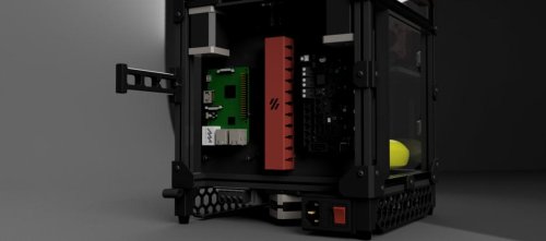
April 23rd...discovered that the new BTT Pi has one of its mounting holes in a slightly different location than the most other branded Pis, so the DIN cleat mount from the official STLs will not fit. Will have to find someone to modify the part CAD so it will work. Being a former IT/server pro, as well as aircraft avionics installer, the typical "rat nest" of wiring seen in most electronics bays throughout many industries drives me nuts, so cable conduits are a must for my build; printing them out of PLA+ using my Snapmaker 2.0 A350. Also came to find out that the PIF parts kit I ordered did not include the needed parts for mounting the Kirigami bed nor the V0 umbilical mod, so will have to get those printed too (no fault to the PIF program here, those are mods, so they are not a part of the standard PIF BOM list).


Last edited:


Mxbrnr
Active member
April 26th...completed assembly of the full frame and gantry, as well as most of the Mini-Stealthburner toolhead with Red Lizard Dragon Standard Flow hotend (had to buy the heater cartridge and hotend thermistor separately). Tuning the belt frequency part is a bit intimidating (sorry, forgot to take a photo of the belt install). Also mounted and wired in nearly all the electronics; waiting on the printed parts needed for the umbilical mod.


Last edited:
Mxbrnr
Active member
April 27th...Assembly complete! Now the most intimidating part, the firmware/software programming; documentation for it is horribly sporadic and splashed all over the internet with little-to-no instruction on the correct order of operations or where to find what you need. I guess that is to be expected with open source DIY machines that can have so many different configurations and mods to them.

 Already in love with this thing. Serial request video submitted and accepted...say hello to V0.2633!
BallisticTech
Active member
Just started my build log on the same kit. Yours seems to be working out pretty well. Thanks for showing it off.
I'm a bit worried about
I'm a bit worried about
- Forgetting to preload nuts
- Getting a square frame
- Belt running and tensioning
- Generally deracking the gantry
Mxbrnr
Active member
The manual is pretty great about helping you to double check the pre-loaded nuts before moving on; several places in the manual where it tells you to do so and shows you where they need to be. Only thing it left out how many nut to pre-load and where if you plan to install a Nevermore filter.Just started my build log on the same kit. Yours seems to be working out pretty well. Thanks for showing it off.
I'm a bit worried about
- Forgetting to preload nuts
- Getting a square frame
- Belt running and tensioning
- Generally deracking the gantry
Getting the frame square took a bit, but using a very flat surface and/or the additional tools like I used is a definite help.
The de-racking is actually really easy with the V0, I don't even have any tips, it's that easy. Nowhere near as bad as with the V2.4
The belt running and tensioning was a bit intimidating to me as well at first, but it's really not as bad as I thought it was going to be. Here again the instructions in the manual are fantastic; I followed it to the letter (including which app to use for the tension freq check) and it really took all the stress out of it.
Few things I noted during my build that I did not mention in these posts...
- You MUST use BTT's CM1 operating system for the BTT Pi, it will not work with the RPi OS like is listed in the build manual.
- The V0 Umbilical frame PCB has a chamber temp thermistor already installed (freakin' sweet!), but sadly the BTT SKR Pico does not have enough thermistor connections to use it, and the stock Formbot kit did not include a pre-fab wire for it. I ended up swapping out the BTT Pi and Pico both for a single unit BTT Manta E3EZ + CM1 that would allow me to use it (in addition to several other advantages (LEDs, extra fans, etc.) without breaking the bank).
- The Dragon hotend hardware kit only included 2 of the proper length screws to attach it to the Mini-SB toolhead (a total of 4 are needed).
- The foot with the hole in it for the Bowden tube? With mine the hole wasn't big enough to fit the tube through without crushing the tube, so I had to drill it out a bit for proper fit.
Definitely keep us posted on your build, and happy to help any way I can.
Last edited:
BallisticTech
Active member
Thanks for all the info!
I definitely appreciate your wiring pictures and notes about cable management. It's a MUST for me to have clean cable management. When I build PCs I often spend about 1.5x times on cable management as building the PC. Granted I'm pretty fast at a basic PC install but I find I end up redoing several parts of the management as I realize I can tuck these wires into this crevice and reroute wire A under wire B so they both have nice straight runs.
Do you recall where you got some of those cable conduits? If they'll show up on a printables/thingaverse search no worries I should be able to find them.
Mxbrnr
Active member
Got those right here actually...Thanks for all the info!
I definitely appreciate your wiring pictures and notes about cable management. It's a MUST for me to have clean cable management. When I build PCs I often spend about 1.5x times on cable management as building the PC. Granted I'm pretty fast at a basic PC install but I find I end up redoing several parts of the management as I realize I can tuck these wires into this crevice and reroute wire A under wire B so they both have nice straight runs.
Do you recall where you got some of those cable conduits? If they'll show up on a printables/thingaverse search no worries I should be able to find them.
Cable Management Duct
Cable Management Duct Little cable duct for hiding the cable. Can print with your desired color to match with your build. Integrated with zip tie mounts. For the cable management manual, I refer to: LDO here. Printed parts There are two version: Standard size: if you have a large size printer I r...
 www.teamfdm.com
BallisticTech
Active member
Question about the z rails and bed assembly. How loose/freely did your bed move before putting the lead screw in.
I've seen some ppl say that with just the kirigami bed frame on it should fall under its own weight. I'm having trouble achieving that.
There's no binding when I move it by hand. It's smooth. But just has enough resistance that it won't fall
I've seen some ppl say that with just the kirigami bed frame on it should fall under its own weight. I'm having trouble achieving that.
There's no binding when I move it by hand. It's smooth. But just has enough resistance that it won't fall
Mxbrnr
Active member
Mine would fall on its own, but there was just enough resistance that it was a stead controlled descent , not a free-fall. I did have to do a "de-racking" of it a couple times as I pieced the frame together.Question about the z rails and bed assembly. How loose/freely did your bed move before putting the lead screw in.
I've seen some ppl say that with just the kirigami bed frame on it should fall under its own weight. I'm having trouble achieving that.
There's no binding when I move it by hand. It's smooth. But just has enough resistance that it won't fall
BallisticTech
Active member
Happen to have any pics of your Mini SB + Umbilical setup? Which mount/strain relief piece did you use? I can't see to find much in terms of pics or 3d models
Mxbrnr
Active member
I just used the ones available in the V0 Umbilical Github... https://github.com/VoronDesign/Voron-Hardware/tree/master/V0-UmbilicalHappen to have any pics of your Mini SB + Umbilical setup? Which mount/strain relief piece did you use? I can't see to find much in terms of pics or 3d models
There are not any photos of it in there, but once you have the parts in-hand it's pretty easy to see how they go on. I am in the process of changing out my strain relief piece for a housing someone recently posted in the FB group that hides the motor and wiring, so I am not able to get any photos of my print-head before. Sorry.
I got you:April 23rd...discovered that the new BTT Pi has one of its mounting holes in a slightly different location than the most other branded Pis, so the DIN cleat mount from the official STLs will not fit. Will have to find someone to modify the part CAD so it will work. Being a former IT/server pro, as well as aircraft avionics installer, the typical "rat nest" of wiring seen in most electronics bays throughout many industries drives me nuts, so cable conduits are a must for my build; printing them out of PLA+ using my Snapmaker 2.0 A350. Also came to find out that the PIF parts kit I ordered did not include the needed parts for mounting the Kirigami bed nor the V0 umbilical mod, so will have to get those printed too (no fault to the PIF program here, those are mods, so they are not a part of the standard PIF BOM list).
View attachment 2342View attachment 2343
GitHub - Sands45/BTT_Pi_Voron_Mount: BTT Pi Voron Mount
BTT Pi Voron Mount. Contribute to Sands45/BTT_Pi_Voron_Mount development by creating an account on GitHub.
 github.com
Mxbrnr
Active member
Here is what I have...sorry for getting it to you late.Mxbrnr- Is there any way you could share the extruder section of your config file?
I finished my hardware build last night, but I'm just getting a buzz from the extruder stepper and I'd love to be able to cross reference a working config to help me troubleshoot.
Thanks!
NOTE: my pin #s will be different than stock because I swapped out the BTT SKR Pico to a BTT Manta E3EZ.

")
