What's new
VORON Design

Register a free account today to become a member! Once signed in, you'll be able to participate on this site by adding your own topics and posts, as well as connect with other members!

LDO 2.4/300 Build Log

So, why am I taking my time finishing this up? Well, I killed a CAN board that I had squirreled away for this build. It was a beta version of the Mellow boards that had a flaw in a switch mounting. TL/DR, too much stress ripped a pad off of the PCB, and my micro-soldering skills need some work. I may still be able to save it, but at some point i have to admit that my time is worth something, and I can’t keep chasing that repair unless it’s just for fun.

I understand that the flaw has since been fixed. So, I’m waiting on a new board to come in. I’m also hoping to stall for long enough that I can snag one of the new blue anodized Revo Voron Edition hot ends that LDO will be releasing “soon”. I’ve seen pictures, and they look super snazzy.

Until then, I’ve just got the bed to mount and a chamber camera to install, and I think that will be it until the CAN board arrives.
 
I have a few extra CAN boards, just about every flavor I could have sent you.
 
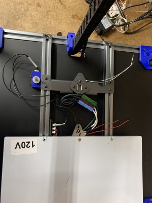
I‘m using the Lightweight Labware kinematic mounts because they are awesome and they make mounting/removing a bed super easy. I have no clue if they do much for print quality, but they are amazing for quality of life! I also like to have quick disconnects above the deck so that I don’t have to flip the printer to remove the bed. I’m using Anderson Powerpole connectors for higher current stuff and Molex Microfit 3 connectors for the thermistor.

Also, the stock Z limit switch pin is too short when you add the kinematic mounts. I think that the stock pin is 30 mm, and I had to put in a 40 mm pin to get a good fit. Your mileage may vary, so be sure to measure your specific printer before using this length pin.

The LDO bed does come drilled for both the Trident and 2.4, so no new holes are required for mounting the kinematic mounts. However, the heater adhesive does slightly interfere with the springs. It’s not tough to make it work, but it is something I thought was worth noting. I didn’t get a picture. :(30954802-A253-4A47-9A71-915F04F6461A.jpeg
 
I just saw an announcement that LDO was changing up their 2.4 kits to include a touchscreen and a Revo Voron Edition hot end. My kit didn’t come with a hot end, which was perfectly fine with me since I have a bunch of spares, but the new black and blue anodized heat sinks that LDO is including for the Revos do look nice. They are also updating the motors to include the StealthBurner motor instead of the Afterburner motor. I'm assuming that the tool head board will be updated as well. All of these are great updates!
 
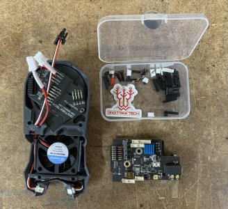
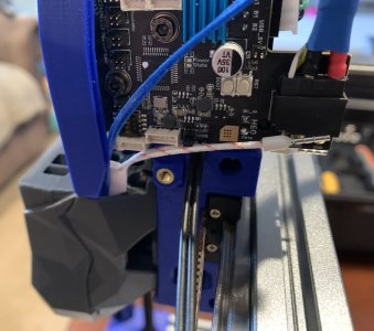
New CAN boards came in! Woohoo! I picked up a couple of the Mellow SB2040 boards as well as one of the BTT EBB SB2209 boards. I’m happy to report that the switches on the SB2040 boards held up just fine and I was able to flash both with CAN boot. I haven’t flashed this SB2209 board yet since it just got here. It’s still slow going, but it looks like shipping from Ali Express is much faster than in recent months/years. I’m not sure what to think about this BTT board. On the one hand, it’s got a TON of options and connectors. On the other hand, damn, are those pins small! I didn’t even try to set the jumpers without grabbing my tweezers. I’m a bit far-sighted, so I needed my super-strong reading glasses to make anything out on the board. I’m REALLY into the XT30+2 connectors that folks have been putting on the CAN boards. These things are pretty robust, and I’m here for that!

I do, however, have a “big” (meaning that it bothers me, but doesn’t make a functional difference) gripe with ALL of the commercial SB toolhead boards. They ALL have male pins on the primary board rather than on the fan sub-board. Good practices say that male power pins should be on the part that is receiving power, not on the side that is supplying power. At this point, it’s become common practice, so I doubt it will change. Sigh.

My other observation is that pretty much every SB toolhead board uses the same fan sub-board EXCEPT for the BTT. This is because BTT includes a CAN pass through so that you can connect a to-be-released touchscreen in front of your part cooling fan. I’ll just say that I’ve never thought of having a display ON the tool head, so points for creativity. However, I know that Badnoob spent a LOT of time and energy optimizing air flow on the fan shroud. Putting a screen in the middle of the fan inlet is not ideal. I’ll be curious to see how the modified shroud that BTT has teased actually works. But also, I’m generally not too excited about trying to read a display that’s moving. So I doubt I’ll do anything with that upcoming display other than test one out if it lands in my lap. I’m sure that it will look cool, but aesthetics that compromise performance aren’t really my style.


F2DA98AD-9009-4610-9C67-8865F8130335.jpeg
 
The SB2209 is the only CANbus board have not tired. Did it come with the pins on the board already? I think I would prefer to solder the fans and LED's to the board.
Also I see why they use the small connectors but dam, they are so hard to work with.
 
The SB2209 is the only CANbus board have not tired. Did it come with the pins on the board already? I think I would prefer to solder the fans and LED's to the board.
Also I see why they use the small connectors but dam, they are so hard to work with.
When HartK first sent me one of the prototype stealthburner breakout boards, I saw the solder-on pads and was not amused. I thought it would be terrible. After actually working with it, I was hooked! I completely agree that I wish that they had the option to solder on. But unfortunately, they are pre-pinned. I am going to give it a spin and see how it works. Keep an open mind and whatnot.
 
Please keep us posted on how you like that SB2209 board. I've been eyeballing the Mellow version of that, but I'm leery of how it does some of the things it does and was looking for a similar form factor board without the challenges afforded by the design choices on the Mellow.

OTOH, it's BTT, and that's a first rev board... Hopefully they learned from the EBB series.

How are the Tridents looking? I've got one in progress also.
 
Next-to-last part of the printer cam in the mail today. Hopefully the last part comes tomorrow! If I’m lucky, I may be pushing plastic but Sunday night! It’s sort of hilarious. This has been the longest in terms of calendar days that it’s ever taken me to build a printer since I’ve just been puttering along and taking my time. But it’s also the least amount of clock time that I’ve had to put into a build. It has been really nice working with a good kit like this.


2DD692D9-FB2D-4A62-AAD8-9A5EF4448B7F.jpeg
797EEDE9-D99E-4FA3-878D-C83D5EC29A81.jpeg
 
Please keep us posted on how you like that SB2209 board. I've been eyeballing the Mellow version of that, but I'm leery of how it does some of the things it does and was looking for a similar form factor board without the challenges afforded by the design choices on the Mellow.

OTOH, it's BTT, and that's a first rev board... Hopefully they learned from the EBB series.

How are the Tridents looking? I've got one in progress also.
I’ll definitely post CAN updates once that gets set up. I’ve got a couple of the Mellow boards as well, so I’ll be running comparisons eventually, but I expect them to perform similarly. I’ve been using two of the EBB 36 boards and have liked them, firmware issues notwithstanding.

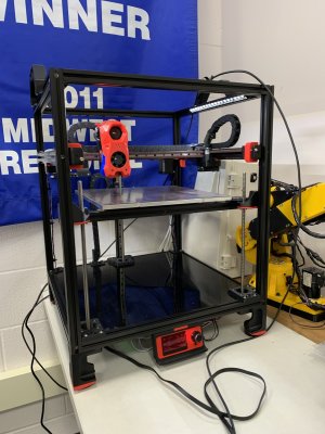
As for the Tridents, one is ready to push plastic, and the other is going to be in a fairly long development process for some experimental parts, so who knows when it will ever actually run! Here is the Trident that I’m helping my son’s robotics team to build. Like I said , it’s almost done! Just need to put the enclosure on and tune it up! 80525320-CD15-4043-9A90-82EADA0D5902.jpeg
 
The SB2209 is flashed and ready to go. I was not able to get CANBoot working on it, and I threw in the towel a little earlier than I really would have liked. I really want to know why CanBoot wasn’t working. In the process, I discovered a couple of things: 1) the documentation for the BTT SB2209 is VERY pretty, and 2) it also has some gaping holes! If you follow the instructions verbatim, you will not be able to flash your boards. Namely, they never talk about the need to install and remove the USB power jumper when communicating with the board over USB. That’s a pretty major oversight. They also left out wiring instructions of Klicky probes. It’s not a really big deal for most folks, but they included wiring for inductive probes and Tap, so why not Klicky? Oh well.

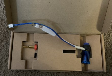
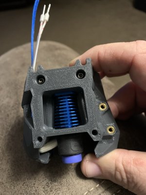
I’m also not impressed with putting the HE connection on the back of the board. Most of the CAN and breakout boards have the heater Jack on the front, so many hot ends will need wire extensions to reach the rear location. This is an LDO Revo new out of the box. It’s clearly designed for a custom LDO tool head since it comes with connectors that aren’t standard from E3D, but I’d expect that the wires would fit literally every other SB toolhead board that I own. If you are moving from a previous EBB 36 CAN board, you are probably OK Since those mount behind the stepper. Still, it’s a little frustrating that I’ll have to splice wires first thing. Pretty minor gripe, but a gripe nonetheless.

I’ve not got it running, so I’ll reserve the “good stuff” comments about the SB2209 until it’s actually turning motors.
7A1E4471-493F-441B-9B7E-6071393EE8FE.jpeg
 
I officially now recommend against the BTT SB2209. The micro connectors are just too small to deal with by hand. I’m pretty darned good at crimping (>95% on the first time for JST XH crimps), and I am only getting about a 30% success rate with my crimps for these tiny guys. I’m going to look into pre-crimped pigtails because I don’t really trust any of the connections that I’ve made so far.
 
It’s alive!!!!!!

Working on debugging configurations and getting all of the macros installed before I put the enclosure on because i Know that as soon as I put the enclosure on, I’ll have to pull it off to run another wire. I already discovered that I’ll need to do something for a Y endstop since I flaked out on that earlier. I was going to go sensorless, but I‘m just not quite comfortable with it yet. Because I’m terrible, not because sensorless homing isn’t good. I’ve still got time to change my mind . . .
(oh, and that’s the in-law’s dog’s crate in the background. He is visiting for the week, so he was keeping me company while I worked on this today.)
C7704007-2BB2-4395-987C-D7CB833F97D2.jpeg
 
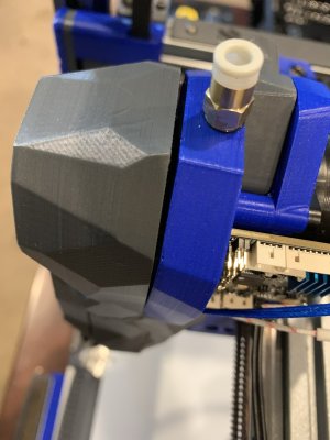
Definitely not happy about this either. The gap here is due to the extra bulk from the connections on the fan shroud breakout board. When HartK first did the
direct solder pads, I thought he was crazy. Now I think its an elegant way to get this solved. Plus, it’s super clean. This definitely leaves something to be desired. C5DFC89E-3F05-4075-86D9-672EA63024DA.jpeg
 
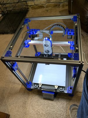
I mentioned earlier that I was building two Tridents while building this 2.4. Here are all three frames—knocked them all out today before taking a break until the new year. The printed parts for one of the tridents are done, and the second batch is about half way done. But I still haven‘t even started printing parts for the 2.4! I’ll start printing them in about a week or so, but for now, this printer will be in the back burner until at least one of the Tridents is done.View attachment 1212
I didn't realize trident frames were so big... What are the bed dimensions?
I still have all the pics from my build. Was going to do a slideshow, but never got to it. Maybe I should, even 2 years later....
 
I didn't realize trident frames were so big... What are the bed dimensions?
I still have all the pics from my build. Was going to do a slideshow, but never got to it. Maybe I should, even 2 years later....
This one is a 300mm bed. I want to say that the width & depth are 460mm, but I may be wrong on that. Size-wise, it is similar to a 2.4 (the three frames I posted at the start of the thread are 2x tridents and one 2.4, all 300 mm bed sizes. I THOUGHT that there was a good chart showing footprint sizes somewhere, but I can't find it now. Also, if you are sizing for a specific space, don't forget to include space for filament! But, yeah. The Tridents are pretty much the same sizes as the 2.4s for the same bed sizes.
 
That V2 is looking good -- as is the Trident for the Robotics Team. Mine isn't quite so far along (I still need to redo some stuff on the rear bed carriage (I put the wrong one on) and I have yet to build the X gantry or assemble the toolhead.

Thanks for the feedback on that BTT SB2209 board. I think I'll just stick to the ebb36 for now -- I hate crimping those teeny JST connectors. My success rate is not even as good as yours.

As far as that fan board goes, I also think HartK was on to something by not pinning those and providing solder pads.
 
Yeah, I would de-solder those pins. Also those tiny connectors are going to deter a lot of people.

Senseless is great! Tuning it only takes about 30 minutes and I don't think I can go back. The only down side is I had to slow down homing a little bit but not much.
 
I’m running sensorless on my V0, so the speed isn’t a huge issue. With a 300mm printer I’m not really happy homing so slowly.
 
Top