What's new
VORON Design

Register a free account today to become a member! Once signed in, you'll be able to participate on this site by adding your own topics and posts, as well as connect with other members!

My First Voron - V0.2r1 (Formbot Kit)

I have the Picobilical on my V0.2 (included in the LDO V0.2 kit). I added a couple of Rainbow on a Matchstick boards for case lighting and use the Picobilical frame PCB as shown in the link @ineligible posted. Here's my definitions config:

Code:
## Neopixel 1 - Frame PCB
[neopixel rgb1] # right
pin: umb:gpio1
chain_count: 10
color_order: GRB
initial_RED: 0.3
initial_GREEN: 0.3
initial_BLUE: 0.3

## Neopixel 2 - Frame PCB
[neopixel rgb2] # left
pin: umb:gpio7
chain_count: 10
color_order: GRB
initial_RED: 0.3
initial_GREEN: 0.3
initial_BLUE: 0.3
 
Im curious as th ethe rear breakout board.. there are multiple inputs for neopixels but the pico has only a single output. The question becomes do I nead to serialize my wiring to them or does it happen on the breakout board
Lighting

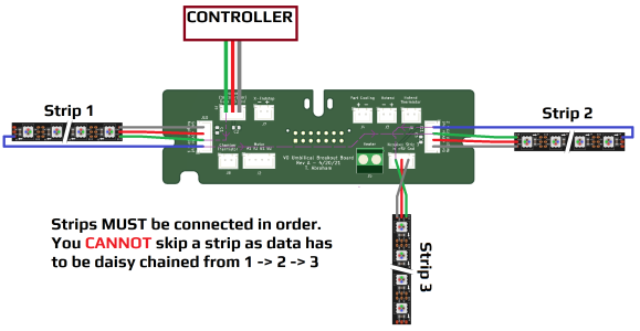
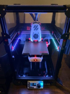
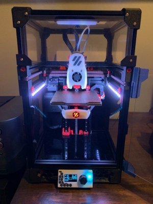
I went for the Rainbow On A Matchstick (RGB) mod (https://github.com/VoronDesign/Voron-Hardware/tree/master/Daylight/Rainbow_on_a_matchstick), mounted under each Y-axis gantry. Most of my prints are quite short in height and I was happy keeping the lighting at the top, plus the lighting position paired well with my camera mount.

The connection for this was via my Klipper Expander and Umbilical PCB.

Code:
[neopixel Matchstick]
pin: expander:PB1
color_order: GRB
chain_count: 20

I used this wiring diagram albeit with Strip 3 unused and Strip 2 without the blue output wire. https://github.com/VoronDesign/Voro.../V0-Umbilical/Images/FramePCB_PixelWiring.png

FramePCB_PixelWiring.png
 
Camera

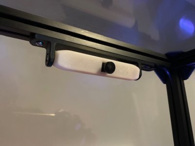
I used a OV2659 module (120 deg FOV) as my camera, connected directly to the BTT Pi via USB. I went through a few mounting options but finally settled on the PanzerObserver system, mounted at the top of . I used a mount for 1515 extrusion available from Printables, but hartk1213 also modified one. Finally I used this modified cover as the OV2659 doesn't have a flash. The picture below is taken with the tophat open, the mount is actually behind the extrusion (not below) and barely noticeable from the front.

IMG_1130.jpg

IMG_1128.jpg

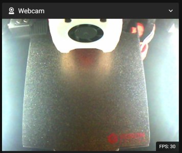
The 120 degree field of view perfectly captures the build area, and is set with manual focus.

webcam.jpg
 
Last edited:
ZeroClick

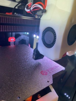
Due to very minor bed levelling issues and laziness, I decided to install some form of auto-bed-levelling. I went for ZeroClick due to it's simple design and preserved print-area versus Klicky. This also allowed me have an almost perfect Z-offset as Z-homing was taken care of using this method. I used Klicky's macro scripts and my config's probe's z_offset is set at 9.400 (Dragon SF with standard Phaetus brass nozzle, printing ABS in a heated chamber). I simply run -0.05 to -0.07 Z-offset for PLA in a cold chamber.

IMG_1126.jpg

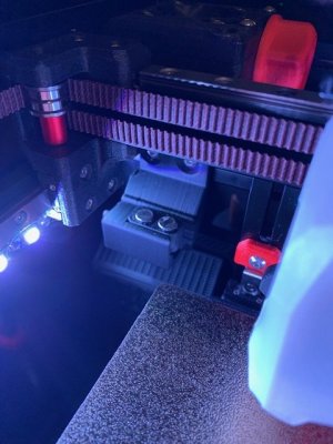
I used ZeroClick's rear mount so that I could still mount the MFNano at the back. However, I found that the X-gantry would interact with it and interfere with sensorless homing. Instead of re-designing the part, I filed down 10mm x 5mm from the rear mount so that the X-gantry could still home all the way and leave enough room for the docking/undocking of the probe.

IMG_1131.jpg

Due to lack of mini-SB mount, I used a modified mini-SB cowl but inlaid it with black for the Voron logo. The electrical feed is through the umbilical via the X-endstop connections.

Overall it took quite some time to have everything set up perfectly, but the quality of life benefits since then have been worth it. Here is my full klicky-specific.cfg

Code:
[probe]
pin: ^gpio22
x_offset: -19
y_offset: 14
z_offset: 9.400
speed: 3
lift_speed: 7
samples: 5
samples_result: median
sample_retract_dist: 2
samples_tolerance: 0.01
samples_tolerance_retries: 10
#drop_first_result: true

[bed_mesh]
speed: 100
horizontal_move_z: 20
mesh_min: 15,17
mesh_max: 100,105
algorithm: lagrange
probe_count: 5,5
zero_reference_position: 80,50
# relative_reference_index: 4
fade_start: 1
fade_end: 10
fade_target: 0
move_check_distance: 3
split_delta_z: 0.0125
mesh_pps: 2,2
#bicubic_tension: 0.2

[screws_tilt_adjust]
screw1: 79,0             #For Long probe
screw1_name: front screw
screw2: 120,100          #For Long probe
screw2_name: back right
screw3: 26,100            #For Long probe
screw3_name: back left
horizontal_move_z: 20
speed: 100
screw_thread: CW-M3
 
Last edited:
MFNano

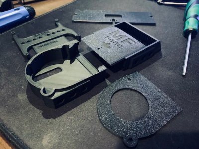
I have the V0 often on the same desk as my workspace and so it was important to have some sort of VOC filtering. I settled with the MFNano which fitted very stealthily in black at the back without interfering with the toolhead. The Bento Mini alternative seemed a bit too bulky for me.

IMG_1084.jpg

IMG_1129.jpg

I hooked this up to the Klipper Expander's mosfet outputs:

Code:
[fan_generic MF_Nano]
pin: expanderA3
cycle_time: 0.010
shutdown_speed: 0
kick_start_time: 0.5

So far, the ABS smells seem to have been greatly reduced.
 
Kirigami Upgrades

The aluminium Kirigami bed which came with the Formbot kit was actually pretty decent. No warping and pretty good shape. I did not encounter any of the issues which @BallisticTech did in his build videos. The only downside was that there was some minor flex, which occasionally led to adhesion issues at the very front of the bed. I also wanted a more sturdy plate for ZeroClick to do it's job. I bit the bullet and bought a steel version from AE (Siboor) and sold my aluminium version on eBay for a cost-free upgrade. The steel version, weighing in at 210g, is so much more robust and barely flexes. Ultimately due to the cantilever design, it would be preferable if all Kirigami beds were made out of steel.

IMG_1091.jpg

I also mentioned the Kirigami PCB which I modified, above. Changing to the steel Kirigami gave me an opportunity to take some photos of the PCB in place.

IMG_1092.jpg

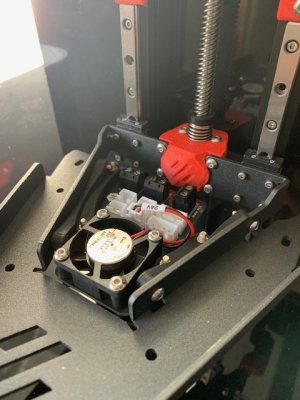
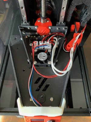
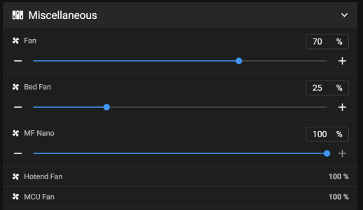
I run the bed fan using one of Klipper Expander's mosfet ports. Heating the bed to 110C with the stock 60W heater and bed fan set gradually from 15% to 25% gets my umbilical's thermistor 20 Celsius above ambient in about 20 minutes. Totally worth it for the huge reduction in heat soak time.

1702941690335.png

Finally I am running Maple Leaf Maker's Stealth Bumper with the Neopixel connection to the BTT Pico. My hope is to add the adaptive LED status macros.

IMG_1097.jpg
 
I bought a kit recently and while I wait for it to come in I have been reading your posts. Thanks for add such thorough details. I have a lot to learn, but you have inspired some ideas to do myself.
 
  • Like
Reactions: Lik
I knew this wasn't finished...

Dragon Burner V8, CANBUS and Screen

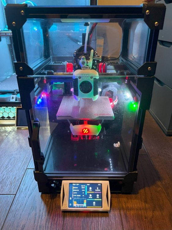
To improve quality (i.e. issue 6) I decided to switch the mini-SB to something a bit more flexible. The DragonBurner V8 was the perfect upgrade, with compatibility with my ZeroClick z-stop. I did lose about 2-3mm of Y-travel, plus I also needed to move the ZeroClick probe mount forward, my remix here. Sherp-Mini was my extruder of choice. One thing to note, I bought super cheap 4010 blowers from AE and they were extremely weak, later replaced with GDStime 9500rpm ones. Buy cheap, buy twice.

I was also frustrated at the rigidity of the original umbilical and so I went with an EBB36 CAN board with Katapult. This interfaced neatly with the U2C Can Module of the BTT Pi. I had experience with CAN on my current V2.4 build, so this was relatively straight forward. Katapult will make things easier in the future.

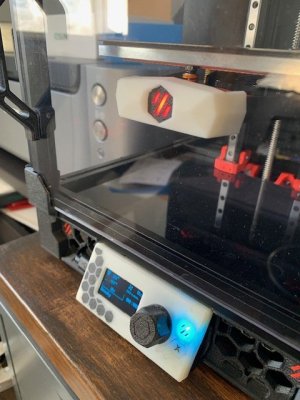
Finally I added a BTT SPI TFT35 screen. This was surprisingly not as responsive as I thought, requiring very firm presses. I would say it is more of a display rather than an interface device.

IMG_2004.thumb.jpg.a62948e6ed1bf32fdc66bc0f4d973b95.jpg
 
Top