What's new
VORON Design

Register a free account today to become a member! Once signed in, you'll be able to participate on this site by adding your own topics and posts, as well as connect with other members!

My First Voron - V0.2r1 (Formbot Kit)

Lik

Active member
Background:

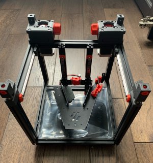
I was one of the many Kickstarters who bought the Creality CR-6 SE in 2020 as their first 3D printer. However, I am probably one of the rarer individuals who only unboxed and started printing with it 2 months ago. After that was upgraded with Octoprint, modded firmware, PEI, dual gear extruder, a new toolhead and various other quality of life improvements, the time came to move this new hobby obsession to the next level. £430 (£70 import tax) lighter, and two boxes arrived to the UK from China from Formbot within a week via Fedex. I am hoping to use the experiences here for a Voron v2.4r2 350mm in a few months time, as well as use this for v2.4's functional parts in ABS.
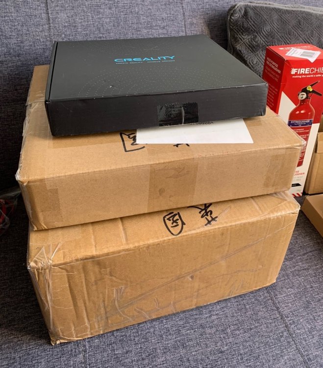
image0.thumb.jpeg.bfd89993f8051bcaaeec9a91b55316fb.jpeg

The Build:
Preparation / Resources:

I have been closely following @Perkeo 's build, trying to absorb everything.

Dmason's V0.1 blog has also been useful: https://3dpandme.com/category/printer-builds/v0-1/

Ballistic Tech has a vlog on this kit here: https://www.youtube.com/playlist?list=PLwWNdxHVFVf1DbI2nGngUB0O9TWeXn2Sx

I am pretty happy with electronics, linux command line and mechanicals. Although had to purchase some crimpers and a couple of 123 blocks for the build. Additional things not included in the Formbot kit: Lithium EP2 grease, Isopropanol Alcohol 99.9%, threadlocker, various connectors (Wagos, XT60, JST).

Voron Discord Profile: Lik#5169
 
Last edited:
The Formbot Kit:

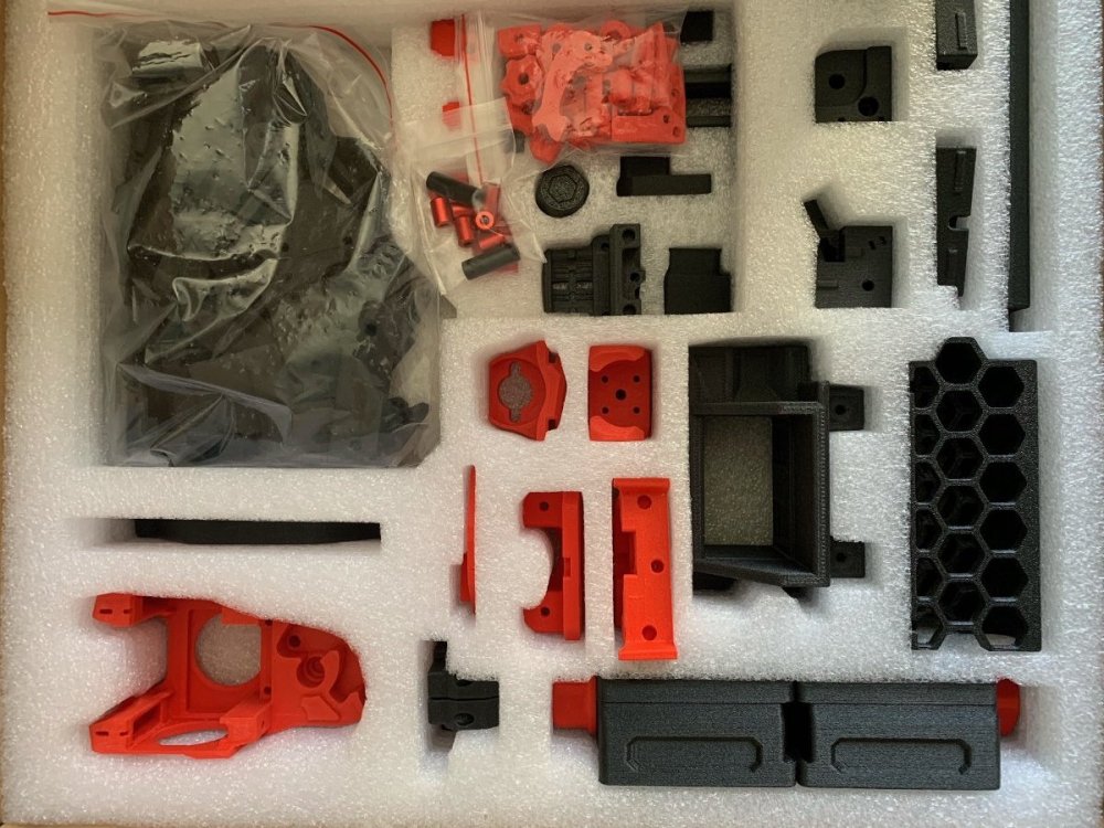
ABS parts come in a separate box with phenomenally good packaging. Each part has it's own customised cut-out.

image3.thumb.jpeg.1d902c9c2a5477c8ab6c1098d27b72ed.jpeg

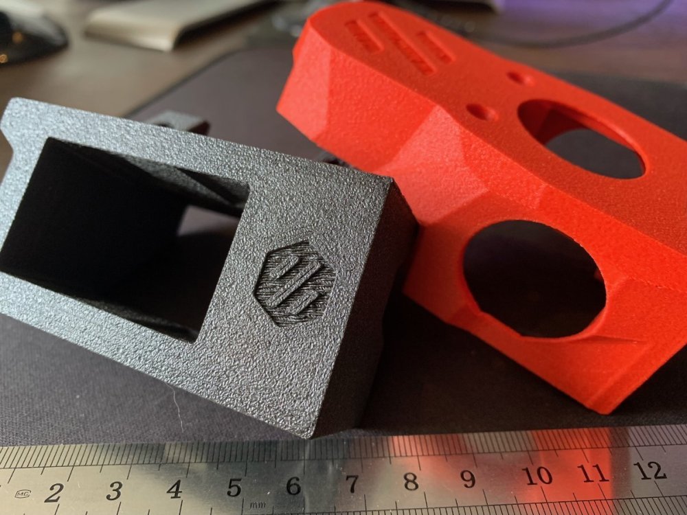
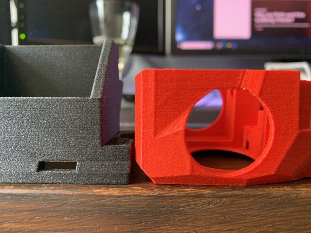
The quality of the parts themselves was impressive. No warping and uniform adhesion.

image1.thumb.jpeg.31f35f73435062a7972f4a42ced9c540.jpeg

image2.thumb.jpeg.7b2903a65e304e8eac3cfa98a7b73cdb.jpeg

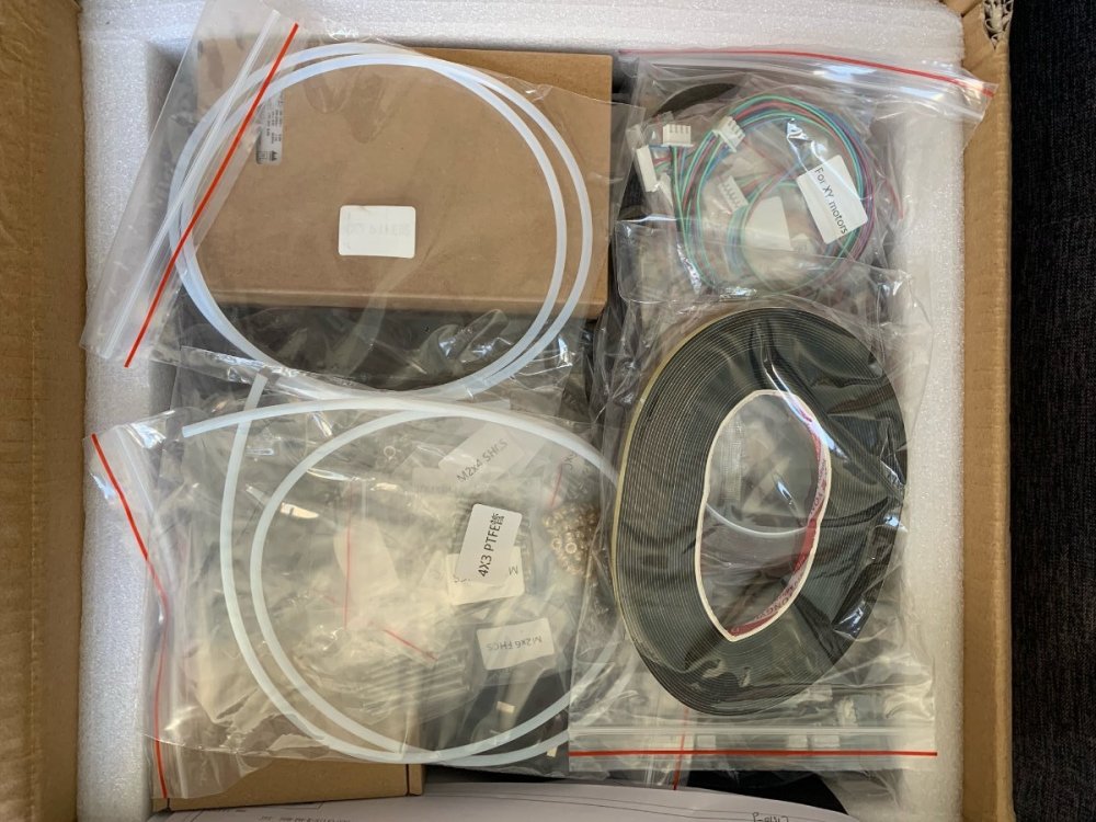
The larger box contained a couple of layers. The top layer comprised of loose bags of fasteners, motion systems and wiring.

image4.thumb.jpeg.db80ff411c4e235f600d2430c8f1da8c.jpeg

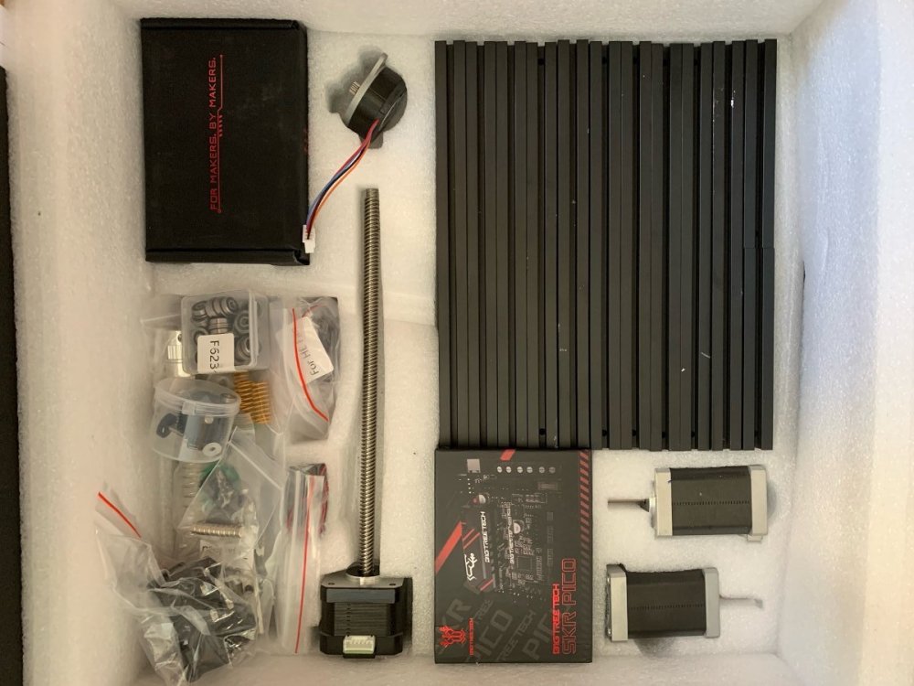
The second lower layer contained customised cut-out sections for the extrusions, motors, electronics. Despite these cut-outs, some of the extrusions managed to free themselves in transit and scratched up. I will try and hide tactically hides these on the build! The 1515 extrusions are anodized after being machined/cut. Whilst the Formbot BOM states "Makerbeam XL", this is not actually the case. The profile is similar to the LDO 1515 extrusions ("D" channel rather than Makerbeam's "T" channel).

image6.thumb.jpeg.eeb95140d4887de93bb359e09b9c8ac0.jpeg

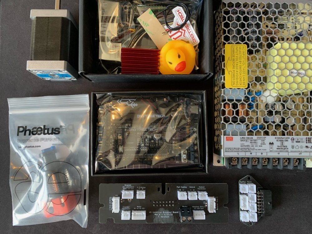
The electronics included in the kit: BTT Klipper Pi (v1.2), BTT SKR Pico (v1.0), genuine Phaetus Dragon SF, Meanwell-branded PSU and Moons steppers. The BMG gears seems quite generic and might be a target for a future upgrade.

image5.thumb.jpeg.56f6aa892f0961b5986265eb391d2bd0.jpeg

Overall I am very happy with the quality of the kit and the USD$60 outlay for all the ABS parts (functional and cosmetic) seemed a good decision. Trying to print ABS in my open-air Creality bedslinger or causing a fire-hazard in a cardboard enclosure would not have been worth the hassle!
 
Please let us know how the printed parts work out. Looking at the one photo of the printed parts up close, there are only 3 perimeters and they look wide, seems they were printed with 0.6mm nozzle. This is not per Voron printed parts guide which requires 0.4 mm nozzle and 4 perimeters. Additionally there is no way to tell how much infill there is and how many top and bottom layers, both of which make the parts stronger if they are printed per Voron settings.
 
Finally made a start and have been at it daily for the past week

Preparation

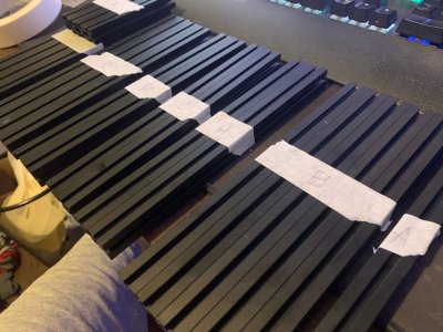
I stole the idea of labelling up the extrusions for easier picking later!

image1.jpeg

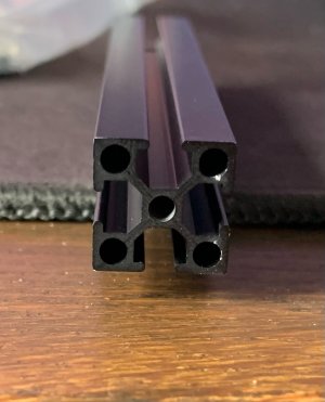
As previously mentioned, the Formbot kit has "LDO" style 1515 extrusions with a D-shaped channel and not the Makerbeam T-shaped channel.

image0.jpeg

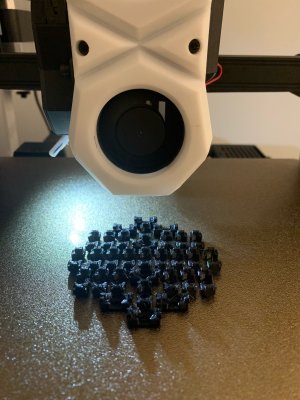
Thankfully this is good news as it means the No-Drops mod works out of the box. Unfortunately despite my best efforts of trying to print ABS on a bed-slinger (eSUN ABS+), there was still significant issues with warping and bed adhesion. I therefore printed them in PETG, knowing that any glass-transition would not affect this non-load bearing part what-so-ever. I did this in 4x plates of 30x drop outs and loaded up all 120.

image2.jpeg

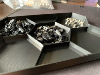
I used the remixed HexTray made stackle and printed it out in vase mode in only an hour...

image4.jpeg

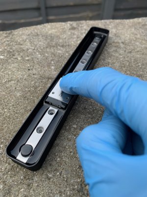
Final bit of preparation was to clean the rails. For this I printed off this linear rail bath, again in vase mode. I could have used the included bag but the bath made it easy to slide the rail up and down. I used mineral spirits for first pass and 99.99% IPA for the final clean. Lubrication was with this lithium EP2 grease applied via a luer-slip syringe.

image3.jpeg
 
The Frame

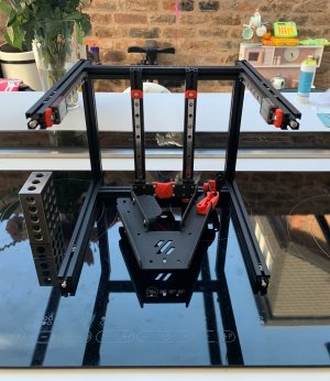
The rail centering tool in the original Voron repository was very useful for aligning the rail to the extrusion. I followed the Voron manual of alternating the bolts for the Z and Y rails. In hindsight, the kit has enough fasteners to fully populate all the rails. I think this would be overkill for Z but I would definitely populate the Y rails fully next time.

image5.jpeg

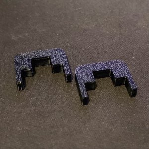
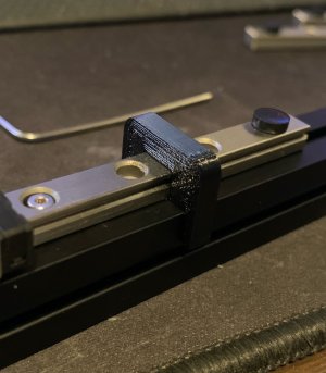
The printed linear rail nut holder from Formbot was so thin and frail that it snapped in a couple of the insertions. I suspect some of the parts are a little over-extruded, which has been mentioned by @pajtaz previously.

image6.jpeg

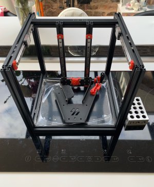
The flattest thing I could find in the house was the induction hob. I hope Neff have their glass tolerances right! A couple of 123 blocks were also useful but in hindsight not crucial. I double and triple checked the pre-loaded nuts, but I also added more for Slim Handles, camera, Nevermore / MFNano, Din rail connectors, and Kirigami PCB.

In hindsight I should have loaded up some for this PSU mount, but some thin square M3 nuts are on their way from Aliexpress which ought to drop in. Also I have since modified the Kirigami PCB so don't need to use the mount for that (see future post).

image7.jpeg

I had to slightly straighten the Kirigami bed from stock, but only very minimally. I also had to re-align the Z-axis linear rails to the extrusion so that both were perfectly parallel and dropped under it's own weight. Probably unnecessary but more for my OCD.

image8.jpeg
 
The Motion System

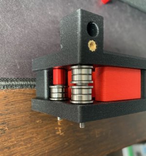
The A/B drives were a doddle. Thankfully I never dropped any of the stacks, but I did use a temperature M3 nut for this exact reason. One issue is that the shims supplied with the kit had thicknesses ranging from single Macdonald's Happy Meal Cheeseburger (0.4mm) to Burger King's Double Whopper (0.6mm). A bit of trial and error was required to have even stack heights.

image9.jpeg

image10.jpeg

The X Axis

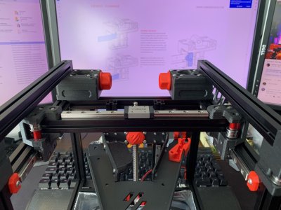
The X rail was a supplied as a specific preloaded rail by Formbot, marked "light preload". Whilst only "light", the difference was very noticeable versus the other rails. All bolts were used for mounting this, with TL-242 threadlocker. In fact, I used thread locker for all the frame extrusions and rail mounts.

I was very surprised and happy to find that there was no sticking or resistance on the Y-rails. The squaring paid off!

image12.jpeg

The Belts

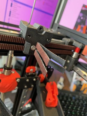
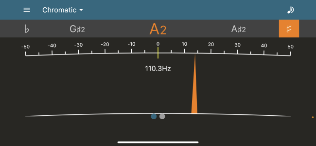
The Gates-branded belt was supplied as a single 3m length. I used the method from Ballistic Tech's build series i.e. a dry run through one side and I cut at 10cm overlap. I then paired this for the second length for a matching pair. With both belts fed and tightened to the same leftover length, I made the magic 110hz. Thanks @BallisticTech . I later found out that I would need to trim these flush to mount the Dragon hotend.

image13.jpeg

image14.png

My current final progress is that I have made it to the electronics and will be flashing firmware tomorrow. However, I am awaiting a modified version of the Kirigami PCB from JLCPCB. Perhaps I'll post the updates anyway but right now I need a whiskey.
 
Just FYI, you will not need the electronics bay separator, since your Formbot kit came with the V0 Umbilical mod, and the frame-side PCB for this will take the place of that separator. You may need to print the mounting brackets (frame and toolhead) for that mod in order to use it. They can be found on the Github repo for it.

I have always found myself wondering what filament and settings are used in the printed parts kit that Formbot sells with these. They look like they are either "fuzzy skin" (probably to hide defects), or some kind of glitter in them. Very interesting. As @pajtaz mentioned, tough to know if they will hold up long-term without knowing if they were printed to the official Voron specs.

Do you know if your kit is the V0.2r1, or the pre-revision V0.2? There are some significant differences in the toolhead and the feet/skirts that are well worth the change. If your kit is pre-revision, I would highly suggest printing the revision parts as one of your first projects once you get it up and running (they will need to be made with ABS/ASA filament).
Hello! Yes, I realised I didn't need the separator when it arrived. I have modified the plate slightly so will post some pictures soon.

I am also very interested in what Formbot uses. I will send them an email as it would be nice to match the accent parts with some mods. Currently printing in eSUN ABS+.

The kit is r1 as it comes with all the June 2023 changes.
 
I have always found myself wondering what filament and settings are used in the printed parts kit that Formbot sells with these. They look like they are either "fuzzy skin" (probably to hide defects), or some kind of glitter in them. Very interesting. As @pajtaz mentioned, tough to know if they will hold up long-term without knowing if they were printed to the official Voron specs.

I have found out that Formbot uses Phaetus aeWorthy™ ABS-GF, which is ABS reinforced with 10% glass fibre. That would explain the surface finish.
 
I have now been printing for a while now, so a big update is due! @BallisticTech has also recently released an unofficial guide to the Formbot 0.2r1 kit which may help future builders. A lot of the info there is gained through his video build series.

image.png.1a12cf0c8b33e91c463adda2d69822f8.png


The Toolhead

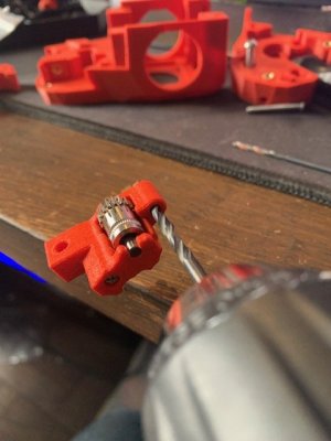
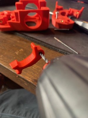
The vast majority of this went together very smoothly. However some intolerances to the printed parts meant a bit of handy work was required with a 3mm drill to make sure the hinge screws spun freely. It has been mentioned that Formbot may not be printing to Voron's official spec (0.4mm Nozzle, 4x walls). However, I haven't found any issues other than this and the filament sensor (see later!). Formbot uses Phaetus aeWorthy™ ABS-GF, in other words ABS reinforced with 10% glass fibre, which would account for the fuzzy texture of the parts.

IMG_1044.jpg IMG_1045.jpg

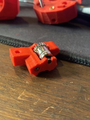
The guidler's pin socket was very tight so a bit of slow and manual reaming was required (slow as to avoid enlarging the socket too much). I also sized the 4x2mm bowden tube using the V0 "swiss army jig" multi-tool.

IMG_1043.jpg IMG_1046.jpg

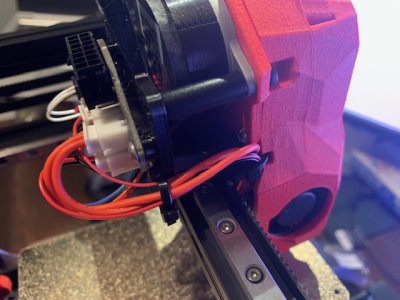
The V0.2 Umbilical toolhead mount was not included in the Formbot kit, surprisingly. Again, I used PETG for now, printing in ABS later.

IMG_1048.jpg

IMG_1049.jpg

IMG_1050.jpg
 
Last edited:
The Electronics Bay

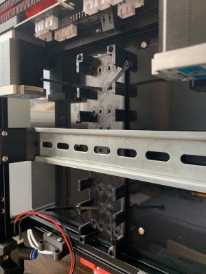
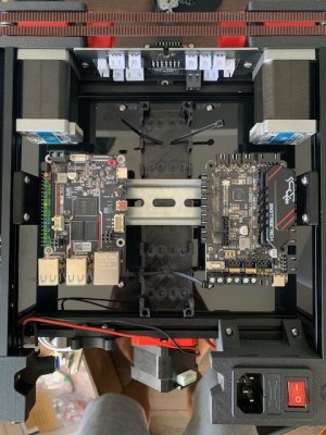
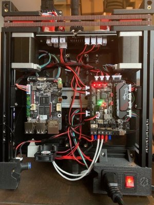
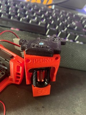
I didn't fancy using VHB tape to mount the electronics and I also kept mobility of the boards in mind. Similarly the PSU was mounted using this adapter rather than tape. I had originally planned to use this DIN rail mount but the push-fit was so tight that I snapped the part. Instead I used this instead with printed M3 washers. I also needed an two extra fans for the MFNano and the bed fan, so a Klipper Expander was required. I could potentially have used Canbus (BTT EBB 36) which would free up a similar amount of ports, but the expander was cheaper and I wanted to use the stock configuration with the option of upgrading later. I modified this Klipper Expander duct, removing the central pillars to fit the DIN rail.

IMG_1056.jpg IMG_1057.jpg

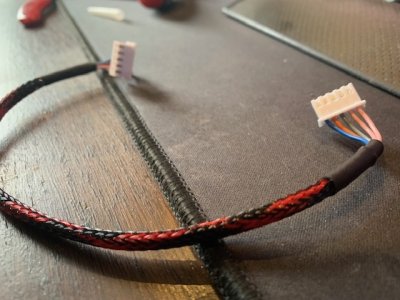
To save USB space (expander, display, canbus port etc) and optimise the link, I decided to connect the BTT Klipper Pi to the SKR Pico via UART. This required a new 5 pin JST connector which I wrapped in matching braided sleeve. This cable also powers the Pi from the Pico.

IMG_1064.jpg

Flashing the firmware wasn't too bad. The process was roughly as follows:

  • Image BTT Klipper Pi. I used the full image, rather than the minimal image, as it included the GPU acceleration by default. I gave this a static IP and hostname via my router's DHCP service.
  • I set the BoardEnv.txt to console=serial to enable UART via /dev/ttyS0.
  • I updated Debian using Putty and updated the rest of Mainsail and it's plugins via the web interface .
  • Flash BTT SKR Pico. I used the PC method as detailed in the Voron documentation. I used serial interface instead of USB.
  • I connected the Pi to the MCU with the homemade UART cable.
  • Flash Klipper Expander: I used the default Github method with the module attached to the Pi via USB.
  • Flash Voron Display: Again, a very easy to follow guide on Github, via USB.
  • Configuration Files: The default Voron Klipper configuration files were pretty self-explanatory. I separated out the macros into macro.cfg with everything (klipperexpander.cfg, pico.cfg, macro.cfg) individually called from printer.cfg. /dev/ttyS0 was used as the Pico UART device (NB: Official Raspberry Pi would use /dev/ttyAMA0).
Here it is all connected prior to the Klipper Expander (i.e. Formbot stock) with the homemade UART cable.

IMG_1066.jpg

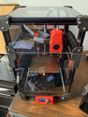
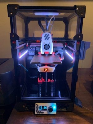
It took a couple of hours to run through Ellis' Tuning Guide, and with that, she was finished and printing the first mod almost perfectly.

IMG_1069.jpg IMG_1075.jpg
 
First Prints / Mods

The printer is lightweight but awkward to pick up and so the first print were Stealth Handles. I had pre-loaded extra nuts for these handles, but ultimately preferred the more subtle look. Using eSUN ABS+, I settled on 230C hotend and 105C bed (240C and 110C first layer). I let chamber reach 40-50C which meant I could use the part cooling fan between 40-80% depending on the shape of the print (overhands, corners, size etc). Pressure advance 0.028 and flow 97%.

To help with moving the machine, I printed this lockable spool holder, using a spare extruder spring for the mechanism.

IMG_1070.jpg

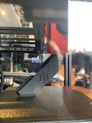
During this time, I noticed that the filament sensor was unpredictable and very dependent on the bend of the filament itself (or the diameter tolerance of the filament). Annoyingly, this caused a lot of paused prints. The micro-switch seemed a bit of an awkward fit on the Formbot part so I decided to reprint the entire part. A genuine Omron switch is in the post to replace the generic bundled switch, but thankfully for now no further false-readings appear to be happening. Ironically, an initial unattended first run of the filament sensor failed due to another filament sensor mis-read (the bed got too cold to resume the part). I turned the sensor off to complete the finished print (!!).

IMG_1083.jpg


Kirigami Breakout PCB / Bed-Fan / Neopixels

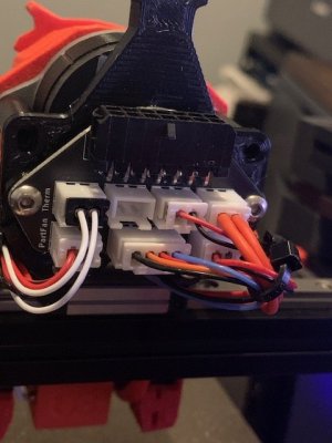
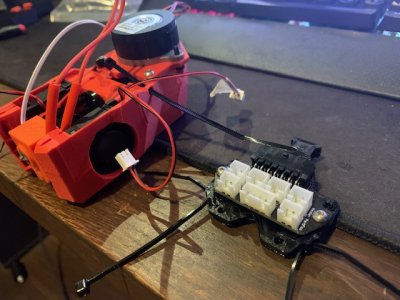
The lengthy heating time of the chamber annoyed me, so I used a hairdryer to boost the chamber. This was not acceptable for the rest of the family (all female) but luckily I spotted the recent release of the Kirigami PCB (thanks @livinhack ). However, I didn't need the umbilical PCB/umbilical and it would also have required Molex connectors which I didn't have. I therefore modified the KiCad files for a personalised solution - a plug in breakout board attached underneath the bed with a 30mm bed fan and Neopixel point. This only required JST connectors and 2-pin screw terminals. The screw terminals allow me to get rid of the Wagos and the JSTs let me run wires from the chain to the PCB, and from the PCB to the parts around the Kirigami (thermistor, heater, thermal fuse, bed fan, neopixel). Not a compulsory upgrade but very convenient. The main goal was the fan!

IMG_1082.jpg

I ordered a minimum quantity through JLCPCB so I have 3 boards remaining if anyone is interested.
 
Last edited:
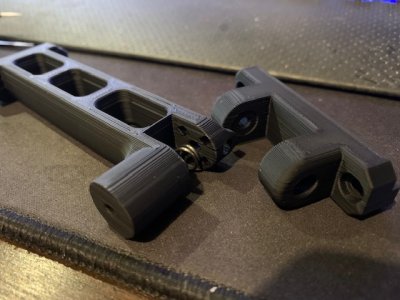
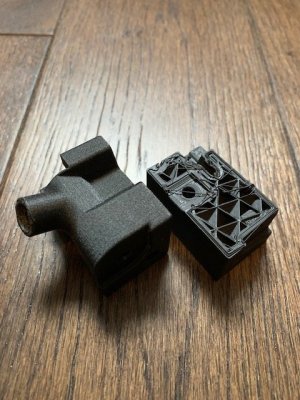
Well, that's definitely NOT the Voron spec 40% infill. Looks closer to 20%, and the way the part separated is indicative of poor layer adhesion. That doesn't bode well for the rest of the parts in the kit. I was afraid of that. It would be advisable to seriously consider reprinting all structural parts immediately. With that said, sadly, eSun ABS+ is notorious for having the same issue of poor layer adhesion and premature failure (regardless of printing parameters), so it it's very recommended to use regular ABS/ASA.

Otherwise, this is looking like a great build! Well done!
No that's my failed part, not Formbot's. You are right though, I'd set it at 20% thinking a foot would be fine, albeit with 4 walls. Perhaps I'll do it to 40% but currently have a long list of other mods to sort out :)
 
Cool build with a nice selection of mods!
Gave me a kick to see my din rail mount mentioned 😃

(I hope to have my own build - also a Formbot kit - done soon 😅)
 
  • Love
Reactions: Lik
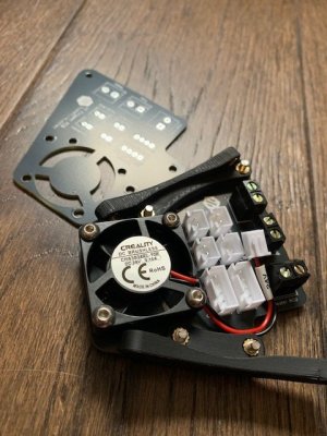
Getting it to the point where I'm happy with most of the mods. Progress report to follow soon!

View attachment 3456
Im curious as th ethe rear breakout board.. there are multiple inputs for neopixels but the pico has only a single output. The question becomes do I nead to serialize my wiring to them or does it happen on the breakout board
 
Top