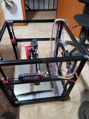
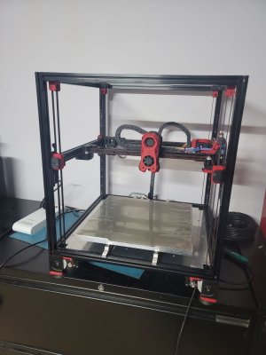
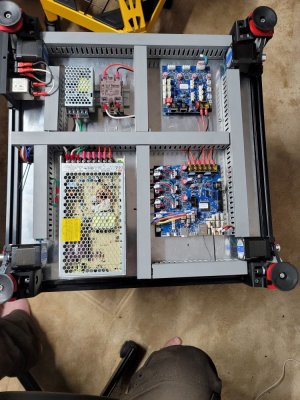
Yes, for higher temp materials. For example, I was getting around 50-55c chamber temps and after adding bed fans (they flow under the bed so no right at the parts, and chamber jumped to about 65c. Enough to keep ASA from warping most of the time.A bit to think about there... So controlling the chamber temp would be an advantage?
VORON Design
You are using an out of date browser. It may not display this or other websites correctly.
You should upgrade or use an alternative browser.
You should upgrade or use an alternative browser.
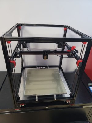
Voron 2.4R2, 350 bed, self sourced, Toronto
- Thread starter Maltasrc
- Start date
I'm not sure I understand what you mean. It looks like you filled below the plate with insulation yes? Would that not reduce air flow around the plate?Additional i isolated via (in kapton tape enclosed) stone wool.
Did that at an other delta before. Increased heating up time and reduced termal losses a lot.
Mike Eitel
Well-known member
No, but I think that the isolation will minimize the losses direction (by fans cooled electronics) colder bottom.
Second i'm no friend of additional artificial thermal turbulences on my parts. Part cooling fans are enough.
I'm mostly printing ASA and warping is a big theme for me...
@Maltasrc Yes, that is my intention. Works like a charm.
Second i'm no friend of additional artificial thermal turbulences on my parts. Part cooling fans are enough.
I'm mostly printing ASA and warping is a big theme for me...
@Maltasrc Yes, that is my intention. Works like a charm.
Warping is caused by the parts cooling too fast. The idea behind the bed fans is to spread the heat around the chamber to reduce warping. The little bit of turbulence it creates does not affect the parts. I think the insulation under a build plate only helps direct the heat up, instead of in all directions.No, but I think that the isolation will minimize the losses direction (by fans cooled electronics) colder bottom.
Second i'm no friend of additional artificial thermal turbulences on my parts. Part cooling fans are enough.
I'm mostly printing ASA and warping is a big theme for me...
@Maltasrc Yes, that is my intention. Works like a charm.
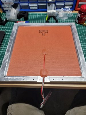
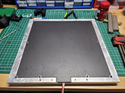
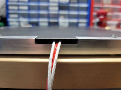
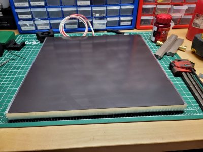
Here is a sectional of what I had in mind. The bottom of the build plate will have a cavity for the heater pad. I will then "Cap" it with a thin metal plate. The cavity will have some insulation inside it to keep the heat moving up into the plate and not down towards the electronics.
For increasing the chamber temps I could add heat fins to the sides of the plate maybe?

For increasing the chamber temps I could add heat fins to the sides of the plate maybe?

WhiteWulfe
Well-known member
What considerations have you taken into place to prevent the thermal fuse from popping?
As for why everyone is mentioning bed fans and the like - it's a simple and effective way to increase your chamber/enclosure temperatures, which is something that ABS tends to like for stronger printed parts. Transfer of heat to the electronics bay in the stock design is relatively minimal, first due to the air gap between the bed and the deck plate, the deck plate itself, and then there's the two fans regularly pushing fresh air through the electronics bay.
As for why everyone is mentioning bed fans and the like - it's a simple and effective way to increase your chamber/enclosure temperatures, which is something that ABS tends to like for stronger printed parts. Transfer of heat to the electronics bay in the stock design is relatively minimal, first due to the air gap between the bed and the deck plate, the deck plate itself, and then there's the two fans regularly pushing fresh air through the electronics bay.
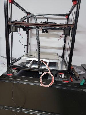
I'm planning to mount the fuse on the outside in the usual place. If the plate gets too hot it should work as expected I would think.What considerations have you taken into place to prevent the thermal fuse from popping?
As for why everyone is mentioning bed fans and the like - it's a simple and effective way to increase your chamber/enclosure temperatures, which is something that ABS tends to like for stronger printed parts. Transfer of heat to the electronics bay in the stock design is relatively minimal, first due to the air gap between the bed and the deck plate, the deck plate itself, and then there's the two fans regularly pushing fresh air through the electronics bay.
Mike Eitel
Well-known member
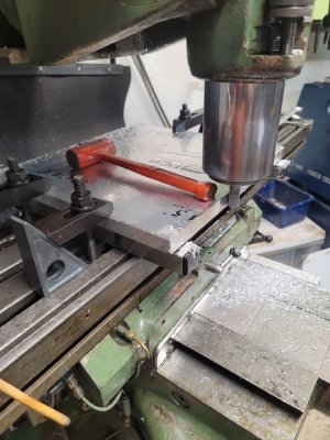
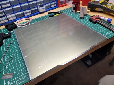
Yeah, I thought of that. I'm monitoring it and so far it seems to be stable. But if it warps I can always get another and try again. The main reason I thought to mill it out a bit is because its twice as thick as needed and it could take a long time to heat up. I figured taking some mass out will help the heat up times and since I got it out of the cutoff section it was really cheap and worth a shot.@Maltasrc
Are you aware that by milling out a structure you induce stress into your plate. Might get some warping over time.
That does look nice. Lucked out finding that piece in the scrap.
Who knows maybe the raised edge will make it more rigid and help keep it straight.
Kinda surprised you didn't machine spots for small magnets into the bed,... something I saw on BIB's utube channel.
In this one, at 30 minutes, he discusses why he chose a mandela bed with the built-in magnets.
BIBs voron build isn't a 350. I think it's a 250mm.
I'm just starting to get this stuff figured out before I decide what kit to buy, behind you a few steps.
Build threads like this are really helping me understand what is required.
Who knows maybe the raised edge will make it more rigid and help keep it straight.
Kinda surprised you didn't machine spots for small magnets into the bed,... something I saw on BIB's utube channel.
In this one, at 30 minutes, he discusses why he chose a mandela bed with the built-in magnets.
I'm just starting to get this stuff figured out before I decide what kit to buy, behind you a few steps.
Build threads like this are really helping me understand what is required.
As I said, I know nothing lol. I never thought of recessing magnets into the bed and it would have been easy enough to do. I guess too late for now but I'll keep that in mind should I have to make another.That does look nice. Lucked out finding that piece in the scrap.
Who knows maybe the raised edge will make it more rigid and help keep it straight.
Kinda surprised you didn't machine spots for small magnets into the bed,... something I saw on BIB's utube channel.
In this one, at 30 minutes, he discusses why he chose a mandela bed with the built-in magnets.
BIBs voron build isn't a 350. I think it's a 250mm.
I'm just starting to get this stuff figured out before I decide what kit to buy, behind you a few steps.
Build threads like this are really helping me understand what is required.
I've been reading a lot on the forums and discord regarding alternatives to the inductive probe. It's all a bit overwhelming and I'm not sure what way to go.
At this stage, the inductive probe is all I have. Should I be holding out and taking another direction or push forward and make a change later?
At this stage, the inductive probe is all I have. Should I be holding out and taking another direction or push forward and make a change later?
WhiteWulfe
Well-known member
I'd say go for the more common route: build stock, then modify later on if you so wish to. It's also easier to troubleshoot the stock design if something isn't working properly, as there are fewer variables.I've been reading a lot on the forums and discord regarding alternatives to the inductive probe. It's all a bit overwhelming and I'm not sure what way to go.
At this stage, the inductive probe is all I have. Should I be holding out and taking another direction or push forward and make a change later?
Similar threads
- Replies
- 40
- Views
- 10K


