What's new
VORON Design

Register a free account today to become a member! Once signed in, you'll be able to participate on this site by adding your own topics and posts, as well as connect with other members!

Formbot Voron 2.4r2 "Bruiser" build log

Bionicall

Member
Welcome to my build log of the "Bruiser" Formbot 2.4r2.
A little bit about me, I am an Electrical Engineer that has been 3D printing for a little over 5 years on a very basic Ender 3.
A mate at work convinced me that I needed to build a Voron, and thus the story starts.
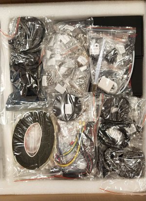
It all starts with a box of bits:
StartingBits.jpg
 
The main reason I am doing a build log is to highlight the mistakes that I have made along the way, in the hope that others can learn from them.

My first mistake was buying an upgrade, without being aware of what that entails.
In this case it meant that I couldn't just follow the manual, this doesn't seem a big issue, but for someone that struggles to seek help, this was quite an big deal.
Credit where it is due, the manuals for the Voron, and Stealthburner are incredibly well written and just beg to be followed.
Well at least until you can't.
My kit came with TAP, toolhead PCB and hardwearing gears, and these things are great.... if you can figure out what they change.
The TAP for example meant that I didn't have a Z-stop, or an inductive probe, and crucially the a/b belts are secured with a different part!
The toolhead PCB means more convenient wiring for the Stealthburner..... if I could figure out what the wiring actually is.
The hardwearing gears are excellent, but it does mean that there is some confusion when it comes to comparing what I have, to what is actually in the manual.

I have worked through these issues now, and I intend to update this post with the links to the TAP manual and for the specific toolhead PCB that Formbot provided.
Tap manual link:
I couldn't find the exact toolhead PCB from Formbot, but with the exception of a slightly moved header to allow a jumper it is the same as:
Yes, I know that is the LDO one.
 
Last edited:
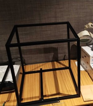
Once the bits have been checked, and investigated I began to realise what I had gotten myself into.
Still the frame was built.
The_Frame.jpg
Was it a mistake to not use threadlocker?
Fortunately I had a glass desktop, so squaring wasn't too bad.
The diagonals even checked out to within a mm or 2.
 
On the frame thread locker isn't really necessary. You do want to make sure to use it on all the grub screws.
 
On the frame thread locker isn't really necessary. You do want to make sure to use it on all the grub screws.
Yeah, I have heard it is quite a debate regarding the frame. However so far in this build, the frame hasn't moved at all (despite multiple flipping up and down).
A note regarding the use of it on grub screws.... this is fine as long as you are good enough not to get one of the pulleys upside down.
Fortunately for me, I caught the error before the threadlocker had fully set, but even so, it was very, very tough to undo the grub screw.
 
I built my 250 Trident last February and it now has 2300 (!!) print hours on it. No loc-tite on the frame screws and it's still rock solid. I just built a V0.2 and no loc-tite there either. However, every grub screw got some.
 
Next up was the Z motors. Well actually it was the heat inserts. I borrowed a soldering iron with a temperature setting so that I could do the heat inserts in a more controlled manner.
This did however mean that I tried to do them all at once.
This was a mistake for 2 reasons:
1. Due to the build being spread over multiple manuals, it is inevitable that you miss some.
2. Trying to find all the bits and parts that need it, when you don't know what the bit/part is or what it should look like is a nightmare for my OCD.

I wholeheartedly recommend that you just buy a soldering iron for yourself for this.

The Z motors themselves were actually pretty easy, noting that the large pulleys that came with the formbot kit look slightly different from the manual (potentially one of the upgrades?), and this did cause a little worry when doing the 'check your work' step.
I am extremely glad that the manuals include these steps, as they prove invaluable for picking up on mistakes before it is too far along the assembly.
 
Keep them posts and pictures coming! Love to read up before I start my actual V2.4 build.

Tonight I test printed the "[a]_guidler_a" and "[a]_guidler_b" of the Clockwork extruder because I understood this is one of the most tight fit on tolerances and thus a good test whether the V0.2 is tuned enough to produce the Voron parts. The fit was too tight so need to tweak somSuperSlicer er settings a little more.

Did you buy your parts or got them from the PIF program or are you actually printing them on your Ender 3?
There are more pictures coming, but I have to transfer them off my phone.
I have been lucky enough that a workmate has made several Vorons, and was happy enough for me to just buy the material and for him to print out the parts.
I wouldn't use the Ender 3, as it isn't enclosed and I wouldn't really want to print ABS with it.

Good luck with your build.
 
For heatset I just got a cheap $15 iron off AMazon that can mount the LDO tool. That's all it does. Now for proper soldering jobs I use the TS-101.

If the Ender is tuned well, you can pull off ABS, just put a box or trash bag over it. I printed up my entire Trident on my Prusa Mini with the shipping box over it. The only issues I had were the larger parts like feet. Those required some glue stick and brims to stop the warping. 90% of the parts on the Trident are still those original Mini-printed parts.
 
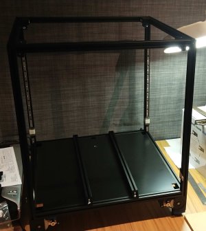
The Z motors, and the rails finished.
I did look at greasing/oiling the rails, but ultimately couldn't find a good recommendation regarding this.
I should still be able to do it retro-actively.

VoronZ.jpg
 
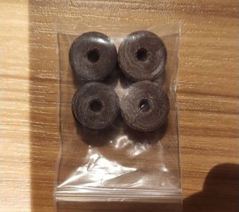
I went to do the bed next and despite doing inventory 3 times, I couldn't find the m4 thumbscrews that are used as spacers.
I did however find:

Bakelite_Spacers.jpg

I initially thought that they were wood, which worried me.
I contacted Formbot, asking about them, and they assured me that they were indeed replacement parts, and that I could use them as spacers.
Some more research and it turns out that they are made from Bakelite, which is a resin filled with wood fibers (hence the wood like appearance).
However it is known for its lack of electrical conductivity and heat resistant properties, the latter being very important for holding up a heated bed.
 
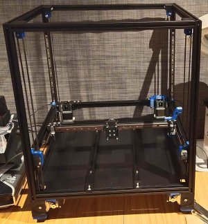
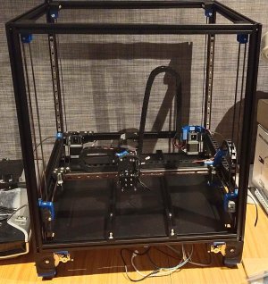
I did the belts and the gantry all in one weekend hit:
Belts_Gantry.jpg
Noting here a couple of things:
First, as mentioned earlier, because of the TAP upgrade the A/B belts are held with a different part.
I am really not sure on how good this part is at tensioning, as the belts have slipped a lot in just moving it around.
Second, as can be seen by the few accent parts I am using a Black and Blue color scheme for the build. Combine that with the size, and now you can sort of see where the moniker "Bruiser" has come from.
Third, as mentioned above about the spacers, for a lot of the build I haven't been confident about the build plate, and as of yet I haven't mounted it.
 
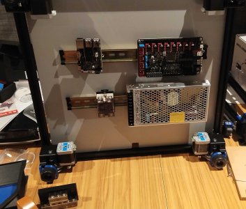
The initial layout of the electronics:
VoronElectronics.jpg
Good to start with, but I would have to shuffle everything around multiple times for the cabling to reach.
This was one area where the documentation was quite poor, and while I can understand why, it still proved one of the most challenging bits of the build.
 
Thank you for doing this, as i am in the same proverbial boat right now, i also got the formbot kit for the 2.4 300 mm variety, the upgrade kit, printed parts ( a verry good deal in my oppinion, nicely printed by formbot in glass fiberABS for a mere 96$/ all parts kit) and a rapido 2 hotend.
At a first glance few things are sub par, the vivedino heat mat is too small at 25/25cm and only 450w and the fans are on the cheap side, for that I got a fysetc silicone heat mat with 96% bed cover, and will sorce some sunons or nidecs locally.
Good luck with your build and see you around!
Thanks for your reply. Sounds like you got some good stuff! I will probably upgrade my hotend pretty soon after everything is up and running as mine shipped with a V6, not bad, but certainly not the best. I like the look of the Rapido 2.
 
The cable chains and the necessary cables are installed:
VoronCableChains.jpg
I had to keep going back to the instructions as the back cable chain didn't seem to fold or work the way I expected, and I did have to learn about unclipping the end piece of the chain to have it face the right way. I still feel that the 'square' piece attached to the back of the gantry isn't quite right, but at least where it is it doesn't stop movement (in the Z direction).
 
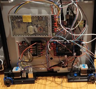
This was my wiring mess, moments before disaster struck:
VoronWiringMess.jpg

Most of the wires actually reached, I had re-cabled the AC side a little (made new wires as the kit ones were too short).
I had been very careful with checking the wiring, doing voltage checks, continuity checks, and general paranoia that comes with testing things for a living.
However, despite the precautions, I blew up the octopus board!
I will save the detailed analysis for a separate post, but it comes back to my original mistake, and not being exact enough.
 
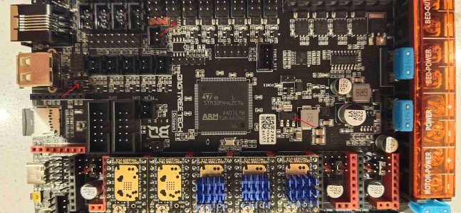
The octopus board, with the magic smoke having escaped:
Octopus_cooked_marked.jpg
Sadly it comes down to two things that I had linked earlier, the TAP and the Toolhead PCB.
The one difference the Formbot toolhead PCB had to the LDO one, is that it had a jumper to select 24V or 5V for the "Probe" (the wiring identifier for the TAP)
The wiring indicated that it should be 5V for the TAP, so that is where I made sure to put the jumper.
This should be all good, right.....
Possibly would have been, if I had noticed that the "Probe" connection on the octopus has its own jumper, to put "V+" on the probe cable.
This jumper was still there, and something that I should have twigged to. This caused V+ (24V) to run up the cable chain, then back down to the 5V on the board side.
This is not good for anything relying on "pulling up" as this will have swamped the logic levels. I liken it to trying to tell the water level from the bottom of the lake.
I have put little red arrows on the most identifiable points where the "magic smoke" escaped.
An expensive mistake as I need a new octopus board.
 
Top