JendaDH
Active member
Hi,
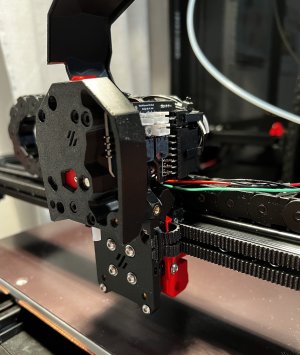
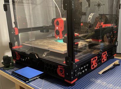
so I have replaced the faulty PT1000 sensor and as precaution I replaced also the 4010 hotend fan. Everything started to work nicely, managed to tune the 1st layer squeeze, started to print some samples so I could see how things work.
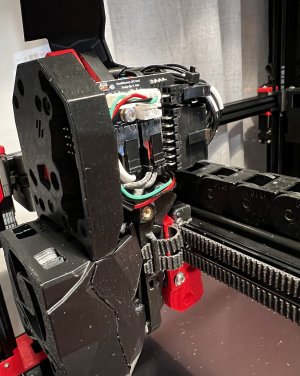
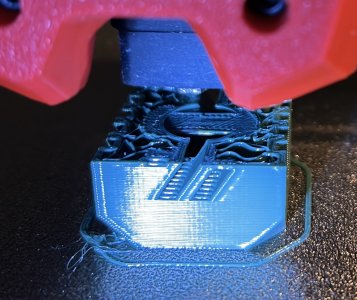
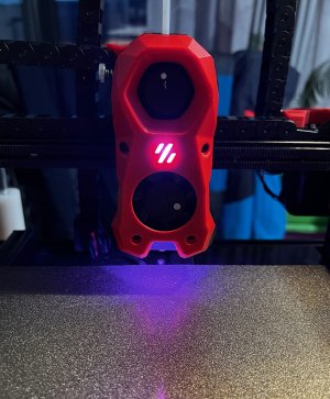
What I am struggling with now are the neopixels in the SB head. They don't want to come alive, checked voltage to the head and it all seems OK. I have set of another three neopixel buttons, so I'll solder them and hook them up to the board directly just laying on the bench to see if I have faulty LED's or where the problem could be.
Printer config sould be fine, I see macros for LED's but nothing happens.
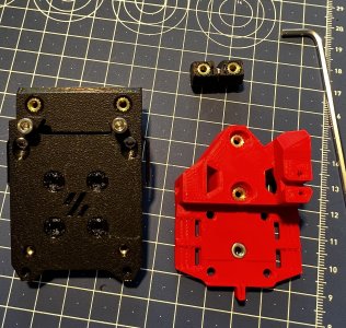
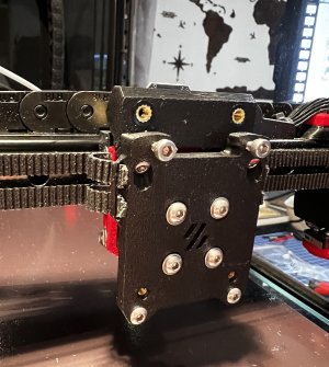
Next on the list is the TAP mod, looking forward to complete that one.
so I have replaced the faulty PT1000 sensor and as precaution I replaced also the 4010 hotend fan. Everything started to work nicely, managed to tune the 1st layer squeeze, started to print some samples so I could see how things work.
What I am struggling with now are the neopixels in the SB head. They don't want to come alive, checked voltage to the head and it all seems OK. I have set of another three neopixel buttons, so I'll solder them and hook them up to the board directly just laying on the bench to see if I have faulty LED's or where the problem could be.
Printer config sould be fine, I see macros for LED's but nothing happens.
Next on the list is the TAP mod, looking forward to complete that one.
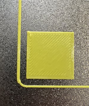
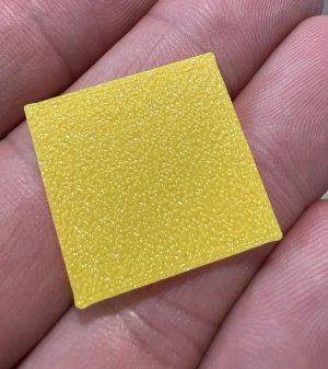


 to see actual prints at the end of the journey ;-)
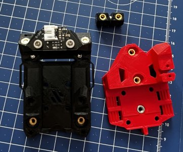
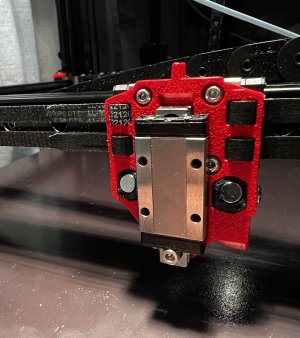
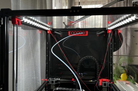
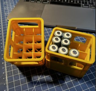
 (yes I had to rotate the GT2 80T pulley, was other way round when I was taking pictures)
") . I built a 3d printer over 9 years ago so it's not so scary. Lots of people out there to help. Best way to learn all about them and help with fault finding too. Enjoy!
. I built a 3d printer over 9 years ago so it's not so scary. Lots of people out there to help. Best way to learn all about them and help with fault finding too. Enjoy!