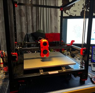
Hi, just a little update before going on holidays.
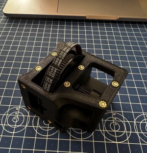
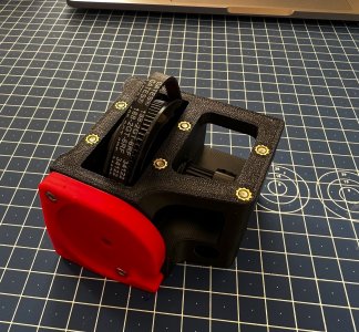
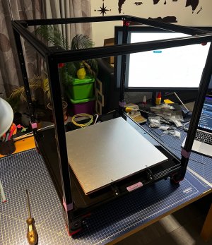
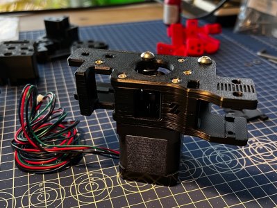
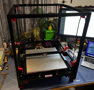
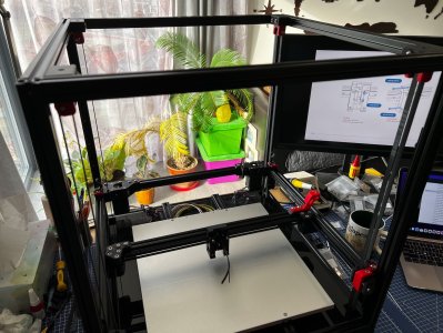
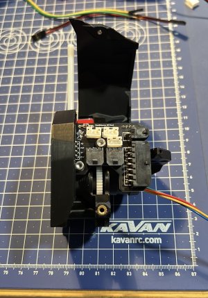
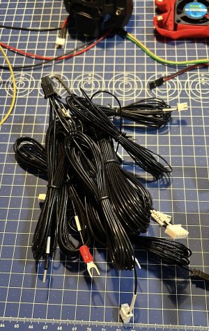
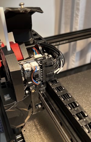
I received SB toolhead PCB so I started to take the temporary "bypass" cabling away and install cable drag chains and route wires through there.
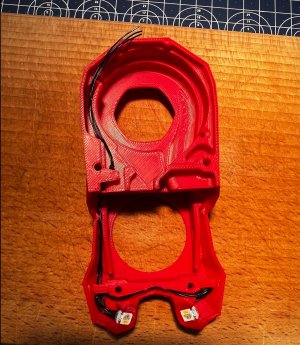
I have Hartk1213 version - two PCB's and could have used a bit more detail on the wiring in documentation. I had to "beep" the wires to see if the HE0 for hotend goes to positive or negative and check the fan connection as well. Mine had jumpers soldered on the fan PCB so it was not clear what is positive or negative. Good that PCB layout images are on Hartk's Github. Just taking extra care not to have any short sice the cabling harness was pre-made in the kit.
From printer operation, I have done the hot end PID, bed PIC, cold extruder calibration, homing, safe Z, tune Z with the paper drag approach, performed QGL, but that I will need to repeat as I still need to "tune" the belts to be in the right spot.
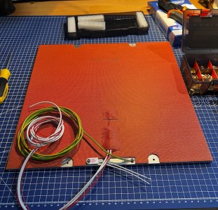
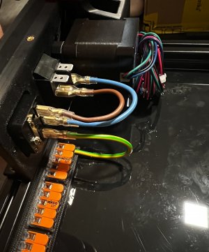
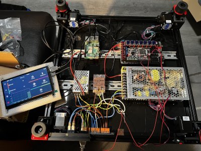
I am glad cables go through cable drag chains, which means I could start tidy things up on the bottom as well. What is planed is reorganising the bed, thermistor and thermal fuse wiring. Local Voron community member was kind enough and printed for me the ABS part that hold the 2 Wago clamp connector. This will go in between the bed extrusions and will make the bed removal easy.
Just before I wanted to verify extruder calibration when actually pushing filament through the hotend, the hotend thermistor gave up on me and is sending havoc values back to the Octopus.
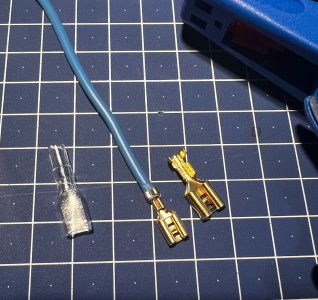
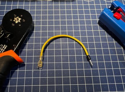
Since I have Octopus Pro with the dedicated port fot PT100/PT1000 thermistor, I tried crimping it with 4 pin connector (I have two wire sensor, but the JST is 4 pin) and this did not work as well.
I even hooked it up back to T0 using the bypass cable I had initially when it worked and did not help either. This leads me to conclusion the thermistor is dead.
I will order replacement + spare and once back home from vacation, I'll swap it and probably use the onboard connector since it is available on the Octopus. The DIP switch was properly set from beginning, also I updated the printer config accordingly to use the MAX sensor.
Oh and yes, I also need to figure out how to work with the 3 RGBW lights in the toolhead ;-)
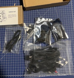
Once I am back, I will also have printed parts for TAP in my mail, so I'll do that upgrade as well. And finally apply for serial number

.
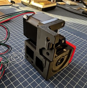
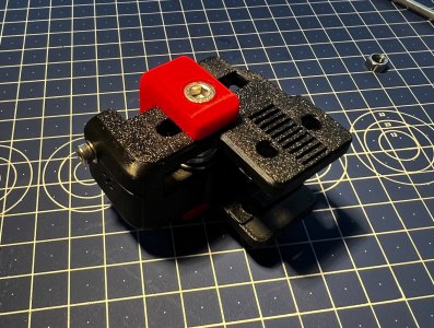
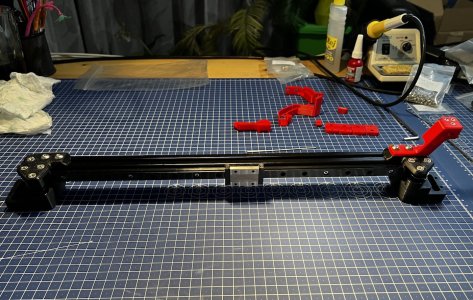
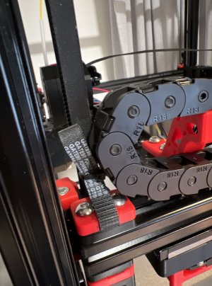
One last thing that needs attention is the Z belt leftover. I clipped it and secured it as per manual, but the cable is still hitting it (as post above). I have removed one link but it still hits the belt leftover. If I remove one more, the chain starts to be a bit under stress in the turn and I don't wan't that.
As suggested by local Voron community, I'll reprint the Z belt clamp with modified design. This will allow me to install panels without worrying they will scrub each other.
See you in a week


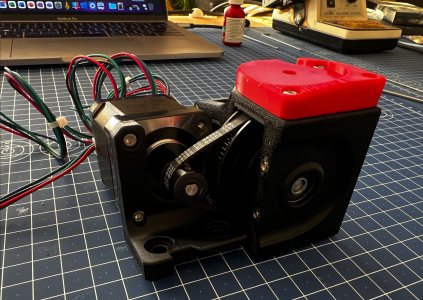
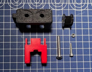
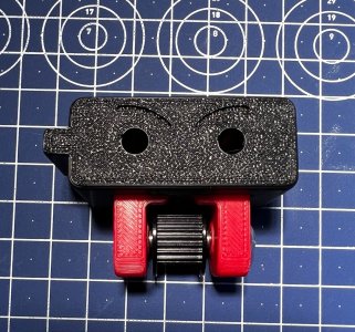
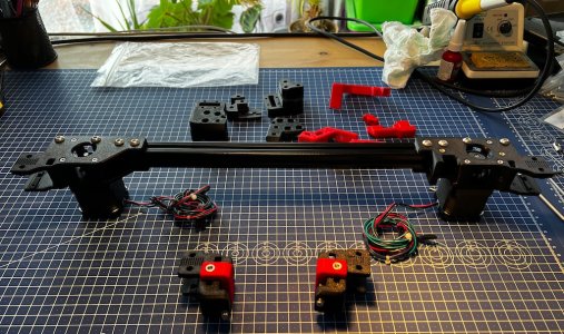
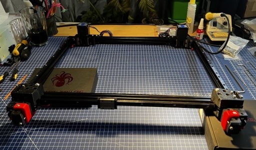
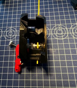
 (yes I had to rotate the GT2 80T pulley, was other way round when I was taking pictures)